
Empfohlen
Empfohlen
Weitere ähnliche Inhalte
Was ist angesagt?
Was ist angesagt? (20)
Andere mochten auch
Andere mochten auch (20)
Ähnlich wie Baja sae india suspension design
Ähnlich wie Baja sae india suspension design (20)
Kürzlich hochgeladen
Kürzlich hochgeladen (20)
Baja sae india suspension design
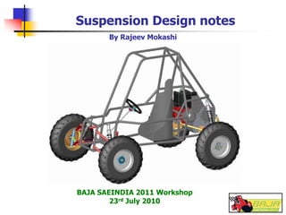
- 1. Suspension Design notes BAJA SAEINDIA 2011 Workshop 23rd July 2010 By Rajeev Mokashi
- 2. Suspension Design by Rajeev Mokashi 2 Acknowledgements Explanation of “Automotive Suspension” www.HowStuffWorks.com SAEINDIA presentation “Suspension design” by Mr Ravindra Deshmukh, Dy GM (R & D), Mahindra & Mahindra, Nashik. 2007 “Suspension Design” presentation by Mr Rob Shanahan, 15-11-2005 “Automotive Suspension design”. Ref: http://en.wikipedia.org/wiki/Automotive_suspension_design “Vehicle Dynamics – Theory & Application” by Mr Reza N Jazar
- 3. Suspension Design by Rajeev Mokashi 3 Introduction What is an Automotive Suspension? An Automotive Suspension is the system of parts that give a vehicle the ability to maneuver. It is a 3 Dimensional Four Bar Linkage What does a suspension do? “The job of a car suspension is to maximize the friction between the tires and the road surface, to provide steering stability with good handling” Ref: www.HowStuffWorks.com
- 4. Suspension Design by Rajeev Mokashi 4 Process of Suspension Design Selecting vehicle level targets Selecting system architecture – type of suspension etc. Choosing location of ‘Hard points’. Selecting rates of the bushings. Analysing the loads in suspension. Designing Spring rates Designing Shock absorber characteristics. Designing structure of each component – Strong, stiff, Light, easy to manufacture and Cheap. Analysing Vehicle Dynamics of the resulting design
- 5. Suspension Design by Rajeev Mokashi 5 Vehicle level targets (main) Ride heights at various states of load Ride frequencies Roll stiffness (Deg / g of lateral acceleration) Distribution of load – front to rear Jounce travel (Bump / Compression) Rebound travel (Droop / Extension) Camber Caster Toe In / Toe Out
- 6. Suspension Design by Rajeev Mokashi 6 Basic Suspension Terminology Ride Height
- 7. Suspension Design by Rajeev Mokashi 7 Desirables for Vehicle level targets Stiffness – Design for maximum torsional stiffness and least weight. This is checked by holding rear shock absorber points & applying torque at front shock absorber points. Provide large suspension travels – typically 250 ~ 300 mm. For typical ATV, ratio of Jounce travel to Rebound travel is 2:1. Provide sufficient ground clearance – more than 200 mm. Use maximum track / overall width allowed. Place wheels at farthest corners. Design to provide tunable features – to adjust Camber, Caster, Toe In, damping forces in shock absorber, spring force on assembly etc. Keep aggregates like Fuel tank, Powertrain etc. as low as possible.
- 8. Suspension Design by Rajeev Mokashi 8 Suspension Architecture Double Wishbone (Equal or Unequal arm) • Lightest weight • Lowest unsprung mass • Greatest adjustability for roll center height, camber, caster etc. McPherson Strut / semi –strut • Compact suspension • Less adjustability Recommendation: Double wishbone – unequal arm
- 9. Suspension Design by Rajeev Mokashi 9 Double wishbone suspension
- 10. Suspension Design by Rajeev Mokashi 10 Hard point location Hard points determine Static settings: Toe (normally Toe In 3 ~ 5 mm) Camber (normally 0.5° ~ 2°) Caster (normally 2° ~ 4°) Roll center height at design load (vis-à-vis CG) caster trail Kingpin inclination (normally 7° ~ 8°) Scrub radius Spring / Shock absorber motion ratios Hard points also affect Handling of the vehicle in dynamic state.
- 11. Suspension Design by Rajeev Mokashi 11 Roll center Roll center moves as suspension travels. Goal of any suspension designer is to minimize Roll Center Migration. Distance from roll center to CG is key to decide roll couple. Lower distance the better.
- 12. Suspension Design by Rajeev Mokashi 12 Design of suspension components Wishbone – Control arms etc. Keep calculations simple. Draw Free Body Diagrams for loads on wishbones. Design for Stiffness Strength follows. Create clean Drawings /Sketches for fabrication. Keep Shapes simple. Calculate stresses for single events – 5 g impact etc. Ensure maximum stress below Yield Stress with good factor of safety. Wishbone pivots / bushes Use rubber bushings or solid bushings. Ensure wishbones move freely and do not rub against attachments / brackets etc. Rubber bushes, if readily available, are preferred. Compliances may be worked out during tuning
- 13. Suspension Design by Rajeev Mokashi 13 Design of suspension components Coil springs / shock absorbers Coil springs over shock absorber designs are easy for tuning, by providing screwed type of spring seats on shock absorber body. Use wheel frequency of 100 ~ 125 cpm for designing spring stiffness. For passenger cars, this frequency is 60 ~ 80 cpm. Choose shock absorber length longer than required – by 10 mm or more, so that it does not bottom out with full bump (2.5 g). Check that coil spring does not become solid at full bump load.
- 14. Suspension Design by Rajeev Mokashi 14 Effect of Suspension geometry on handling of vehicle Twitchy in back, tires wear on outer edge.More oversteer, more forgiving limit More positive camber in rear wheels More oversteer, car feels twitchy in back, tyres wear out on the inside edge Less oversteer, more rear grip / limit -3 degrees More negative camber on rear wheels Poor braking, car is road crown sensitive, twitchy, tires wear out on outer edge. More understeer, can make the tyres last longer More positive camber on front wheels Poor braking, car is road crown sensitive, twitchy, tyres wear out on the inside edge Less understeer /limit -3 degrees More negative camber on front wheels Understeers, then oversteers as car bottoms out with a jolting ride. Less oversteerRear spring rate decrease Too much oversteer, hop in corners, twitchy. More oversteerRear spring rate increase Oversteers. then understeers as car bottoms excessively with jolting ride Less understeerFront spring rate decrease Terminal understeer, front of car hops in corners. More understeerFront Spring rate increase Symptom of too much adjustment Affect on vehicle handling, limit adjustment Suspension adjustment
- 15. Suspension Design by Rajeev Mokashi 15 Effect of Suspension geometry on handling of vehicle Not usableNegative front caster Can increase understeer, increases steering efforts. Helps both stability, steady state cornering and turn in. Limit 6 degrees positive. Positive front caster Not good for street driving, causes lift throttle oversteer, car makes violent side to side rocking motions in rear. Helps car rotate, useful on tight low speed courses and slalom events (limit 3 mm total toe out) Toe Out rear Twitchy under braking, car is road crown sensitive, car wanders on straight road. Car turns in well, good in FWD cars. ( limit 6 mm toe out) Toe Out front Weird slow rocking movement in back, feels slow but unstable. Less likely to oversteer when throttle is lifted Toe In rear Car has slow twitchiness under braking, feels odd, wears out outer edge of tyres Car is stable while going straight. Turn in is average. Toe In front Symptom of too much adjustment Affect on vehicle handling, limit adjustment Suspension adjustment
- 16. Suspension Design by Rajeev Mokashi 16 One last word ……. Figuring a suspension of car is almost entirely a matter of making useful approximations. It is not an exact science. But neither it is a blind application of rule of thumbs. - Quoted by Mr Ravindra Deshmukh R & D, Mahindra & Mahindra