SlideShare ist ein Scribd-Unternehmen logo
1 von 37
Downloaden Sie, um offline zu lesen
3D PRINTER DESIGN USING
FUSED DEPOSITION MODELING (FDM) TECHNIQUE
By
Name Roll No. Registration No.
SURAJ KUMAR SINGH 11700315120 151170110305
SATYA PRAKASH PARIDA 11700315086 151170110271
SUBHASHIS DAS 11700315112 151170110297
ANKSHUK RAY 11700315020 151170110205
A comprehensive project report has been submitted in partial fulfillment of the
requirements for the degree of
Bachelor of Technology
In
ELECTRONICS & COMMUNICATION ENGINEERING
Under the supervision of
Assistant Professor (RCCIIT)
Mrs. Saraswati Saha
Department of Electronics & Communication Engineering
RCC Institute Of Information Technology
Affiliated to Maulana Abul Kalam Azad University Of Technology, West Bengal
Canal South Road ,Beliaghata, Kolkata- 700015
21st
MAY, 2019
CERTIFICATE OF APPROVAL
This is to certify that the project titled “Design and Development of 3D Printer ”
carried out by:
Name Roll No. Registration No.
SURAJ KUMAR SINGH 11700315120 151170110305
SATYA PRAKASH PARIDA 11700315086 151170110271
SUBHASHIS DAS 11700315112 151170110297
ANKSHUK RAY 11700315020 151170110205
for the partial fulfillment of the requirements for B.Tech degree in Electronics and
Communication Engineering from Maulana Abul Kalam Azad University of
Technology, West Bengal absolutely based on his own work under the supervision
of Mrs. Saraswati Saha. The contents of this thesis, in full or in parts, have not
been submitted to any other Institute or University for the award of any degree or
diploma
Optional in case of external supervisor
…………………………………………… ……………………………………………
Dr./Mr./Ms./Mrs. Dr./Mr./Ms./Mrs.
Designation and Department Professor, Dept. of ECE
Institute RCC Institute of Information Technology
……………………………………………
Dr./Mr./Ms./Mrs.
Head of the Department (ECE)
RCC Institute of Information Technology
DECLARATION
“We Do hereby declare that this submission is our own work conformed to
the norms and guidelines given in the Ethical Code of Conduct of the Institute and
that, to the best of our knowledge and belief, it contains no material previously
written by another neither person nor material (data, theoretical analysis, figures,
and text) which has been accepted for the award of any other degree or diploma of
the university or other institute of higher learning, except where due
acknowledgement has been made in the text.”
……………………………… ………………………………
SURAJ KUMAR SINGH SATYA PRAKASH PARIDA
(ECE2015/019) (ECE2015/020)
Registration No: 151170110305 of 2015-2016 Registration No: 151170110271 of 2015-2016
Roll No: 11700315120 Roll No: 11700315086
……………………………… ………………………………
SUBHASHIS DAS ANKSHUK RAY
(ECE2015/006) (ECE2015/037)
Registration No: 151170110297 of 2015-2016 Registration No: 151170110305 of 2015-2016
Roll No: 11700315112 Roll No: 11700315120
CERTIFICATE OF ACCEPTANCE
This is to certify that the project titled “Design and Development of 3D
Printer ” carried out by:
Name Roll No. Registration No.
SURAJ KUMAR SINGH 11700315120 151170110305
SATYA PRAKASH PARIDA 11700315086 151170110271
SUBHASHIS DAS 11700315112 151170110297
ANKSHUK RAY 11700315020 151170110205
is hereby recommended to be accepted for the partial fulfillment of the
requirements for B.Tech degree in Electronics & Communication Engineering
from Maulana Abul Kalam Azad University of Technology, West Bengal
Name of the Examiner Signature With Date
1 . ……………………………………………………………………………………
2 . ……………………………………………………………………………………
3 . ……………………………………………………………………………………
4 . ……………………………………………………………………………………
CONTENTS
TOP PAGE……..……………………………………………………………..1
CERTIFICATE……………………………………………………………….2
DECLARATION……………………………………………………………..3
CERTIFICATE OF ACCEPTANCE…………………………………………4
CONTENTS…………………………………………………………………..5
ABSTRACT…………………………………………………………………..7
LIST OF COMPONENTS USED…………………………………………….8
LIST OF ABBREVIATIONS………………………………………………...9
LIST OF FIGURES………………………………………………………….10
LIST OF TABLES…………………………………………………………...11
1. INTRODUCTION…………………………………………………….12
2. PROJECT REPORT AT A GLANCE………………………………...12
2.1 Definition………………………………………………………….13
2.2 Design……………………………………………………………..14
2.3 Problem Statement………………………………………………...14
2.4 Possible Solution…………………………………………………..14
2.5 Simplified Block Diagram………………………………………....15
2.6 Working With Files………………………………………………..16
2.7 How 3D Printer Works…………………………………………….17
3. COMPONENTS DESCRIPTION……………………………………..17
3.1 Frame………………………………………………………………17
3.2 Extruder……………………………………………………………18
3.3 Stepper Motor……………………………………………………...19
3.4 A4988 Motor Driver……………………………………………….20
3.5 Plastics……………………………………………………………..21
3.5.1 Polylactic acid plastics………………………………………21
3.6 Software Needs To install………………………………………….22
3.6.1 Arduino Software...………………………………………….22
3.6.2 Sli3r software………………………………………………..22
3.6.3 Proterface software…………………………………………..22
3.7 Basic electronic connections……………………………………….22
3.8 FrameWork...………………………………………………………23
4. PRESENT 3D PRINTING TECHNOLOGY………………………….24
4.1 Fused Deposition Modeling(FDM)……………………………….25
4.2 Selective Laser Melting(SLM)………………………………….....26
5. WORKING OF THE DEVICE……………………………………….26
6. FINAL RESULTS....…………………………………………………..33
7. FUTURE SCOPE AND APPLICATONS…………………………….35
8. CONCLUSION………………………………………………………..36
ABSTRACT
Nowadays 3D printing has become a big boom. This technology is not only
used in industries but also used at those places where the prototyping is an
important constraint .This project aims to develop a 3D printer that not only
counts for a cost effective output but a product that can be used by each and
every one. After this project gets a final touch it will benefit the common
people where the cost effectiveness is very crucial. Many 3D printing
technologies are available to build a 3D object but this project aims to use that
3Dmanufacturing process that gives a cost effectiveness solution at a low
wastage of printing material.3D printers capable of outputting in color and
multiple materials already exist and will continue to improve to a point where
functional products will be able to be output. Printing rather than “3D printing”
has bought a radical change in the world we live. Now a days 3D-Printing has
gone from developing a factory need object to a medical need artificial bones
and making it a “low cost” is the new area of development. Gone are those
days where the 3D objects were brought from the market, who would have
thought that this 3D printer would do the same work with a low cost!!!
“Once We have this fascinating 3D printer, do not forget the fact this is a low
cost one!!”
LIST OF COMPONENTS USED
NAME QUANTITY
Arduino Mega with RAMPS 1.4
Controller
1
Extruder kit
0.4mm extrusion head
1
Endstops 3
A4988 stepper motor driver 4
PLA & ABS filaments 1 KG
Heat bed 1
SMPS 1
UPS 1
Frame ,bearings,pulley,MK8 rods
LIST OF ABBREVIATIONS
Name Abb.
PLA Poly(lactic acid)
or polylactic acid or
polylactide (PLA)
ABS Acrylonitrile butadiene styrene
- thermoplastic polymer
SMPS switched-mode power supply
LIST OF FIGURES
Figure 1 Ideal Nozzle Placement
Figure 2 Block Diagram of the Entire System
Figure 3 STL File
Figure 4 Frame
Figure 5 Extruder
Figure 6 Stepper Motor
Figure 7 Driver A4988
Figure 8 Simplified connection of Driver and controller
Figure 9 ABS Plastic
Figure 10 PLA Plastic
Figure 11 SMPS
Figure 12 A4988 Driver
Figure 13 A4988 Driver heat sink
Figure 14 Arduino ATMega 2560
Figure 15 Connection of Arduino 2560 and Ramp 1.4D
Figure 16 Running motors through electronics
Figure 17 FrameWork
Figure 18 Fused Deposition Method
Figure 19 SLM
Figure 20 Slicing Procedure
Figure 21 Pronterface action
Figure 22 Endstop position
Figure 23 Final Results
History of printing starts from the duplication of images by means of
stamps followed by the flat bed printing process in 18th century. In mid of the
19th centuries color printing called as Chromolithography became very popular.
A revolution occurred when the print workings, specifically a 2D printer was
used as a peripheral device, which made a persistent human readable
representation of the graphics a text in paper. After some years the concept of
3D printer starts evolving, a new way to look at the past printing technologies.
Our report emphasizes on the design and development of a low-cost 3D
printer. 3D printer basically is concept to make or print the objects layer by
layer and thus making it so called “Three dimensional”.
Nowadays 3D printer available is of higher costs that is due to the
printing technology used and the material used in 3D printer, so this project
sparks upon making the 3D printer low cost by using the scrap materials and
designing a frame for the 3D printer.
The main aim of this project is to make the 3D printer available to a
common man making this equipment easy to operate and automate working
once the command and specific design is given to this device. So operating time
will automatically decrease as it can handle the task without any human
intervention. This also makes this device reasonable and approachable to
everyone this project. This project deals or in other words targets the people
who has cost as a main constrain and thus making a 3D printer useful in school
laboratories, making imitation jewelry for women, automobile industries,
making a prototype material in industries etc.
This chapter deals with the introduction, design and goal and the basic
working principle of how the project works with a simplified block diagram and
its brief explanation. Thus, with this chapter the main motive of the project
would be clear with the basic understanding of the project.
1. INTRODUCTION
2.PROJECT REPORT AT A GLANCE
2.1 Definition
3D Printing technology is an additive manufacturing technology where a
three-dimensional object is created. This technology is a rapid prototyping
technology.
2.2 Design
The design structure that this project aims is a FDM Model.
2.3 Problem Statement
The present 3D printing technology is very time consuming with a high
manufacturing cost. This project aims not only to reduce the cost of the 3D
Printer but also working upon its accuracy and time constraints.
2.4 Possible Solution
The possible solution is designing a frame and using only the most important
materials and using the printing technology that minimizes the wastage of
plastic to give maximum efficiency to the product output.
FIGURE 1
2.5 Simplified Block Diagram
FIGURE2.BLOCK DIAGRAM OF THE ENTIRE SYSTEM
This above block diagram describes the basic working of the product. As shown
in above block diagram:
Firstly, a 3D object is designed using a CAD Tool and then is converted
in such a file format specifically a G-Code using software’s like FDM that is
understandable by the electronics that mainly includes the Microcontroller.
Input is given to the electronics that give commands to the motors according to
the design in the CAD Tool. The mechanical components including motors,
extruder works accordingly and thus a layer by layer object is printed (in
layman language plastic is glued) on the print plate or glass plate. After the 3D
object gets cooled to a certain temperature the final end product can be taken
out. In this way the simple process works to build a 3D object. Thus, a
prototyping of the project also becomes easier as the specified or the required
designed on an initial stage is formatted on a CAD Tool and your printer starts
to print! To get a change in the final product structure the design in the CAD
Tool only needs the change, rest all the working remains unchanged.
3D OBJECT
DESIGN
CONVERSION
TO RELEVENT
CODE
INPUT TO THE
PROCESSOR
MECHANICAL
PROCESSINGS
PRINTING
3D OBJECT IS
READY
2.6 Working with Files
FIGURE3.STL FILE
There are several different file types used in 3D Printing file extensions
that includes. stl, .g-code, .factory. STL and OBJ files are the output from the
CAD Software’s. After the STL and OBJ files are imported the next work is to
add the process. This process adds all the information that how the object is
sliced and printed on the print plate including the settings of the extruder, infill,
temperature, supports etc. After this process is saved and exported an FFF file is
created. If we want to again change the process settings for example changing
the printing speed, infill percentage etc. There comes option of “Edit Process
Settings”. After making such modification the OK option is clicked to save the
changes .G-Code / X3G files gives the instructions for the printer. G-code tells
the machines how much to move, where to move, how fast to move. Such types
of settings are also called as 3D Printing Tool Path. G-code uses plain text
format while the X3G uses binary language which is used by the machine with
the maker boat type firm wares. When the option Prepare to Print is clicked
the3D model will automatically get converted into 3D Tool paths for the
machine. Factory files is a combined file to retain the simplify 3D Project. It
offers a unique way to save all the data about the project into a comprehensive
file called as “Factory File”. This file includes copy of 3D models been
imported, their positions on bed, process settings etc. 3D Printers typically uses
software that “slices” a 3D model into layers and then the software generates a
G-Code that extrudes the plastic to fill each layer. Mostly slicer software works,
CAD program is compatible of producing
STL’s.
2.7 How 3D Printer Works?
The basic working principle of 3D printer is to print the object layer by
layer fill the targeted object design and to finish the printer has a frame structure
and three axis x y and z axis that moves left to right front to back and up and
down. The component called extruder which is responsible for feeding the
plastic to print and melt the plastic. To print the plastic layer the movement of
the extruder and stepper motor need to be controlled for that PWM generated by
the Arduino is used, the g-code generated is used to drive the axis accordingly
with help of CAD tools targeted objects are designed and converted into g-
codes with the help of software like FDM and being given to electronics that
includes motor which is placed on the frame according to the frame design.
According to the commands given to the electronics motor works and through
the help of extruder which is also running through the motor melts the plastic
accordingly on the print plate.
The plastic material used in this project is bio degradable plastic
materials. After the object is finished the final object is taken out. In this way
the process started with the designing object specifically a 3D object and ended
with the generating the same 3D object same object in front our eyes!
This chapter includes the description of various different components
used in the development of the system project. It is really very necessary to
describe the features of the components that are used in the designing of the
system. This chapter includes the brief description of the components along
with their pin configuration and different features.
3.1 Frame
Selection of frame is an essential part for system designing. This frame
gives the support to the printer. All the axes of the motor added to this frame.
The threaded rods are mounted on this frame and rubber strips controlled by
motor action.
3.Component Description
FIGURE4. FRAME
3.2 Extruder
FIGURE5. EXTRUDER
Extruder consists of two parts, a cold top part that feeds the plastic
filament, hot part at bottom that melts and extrudes the plastic. The speed of the
extruder head may also be controlled, to stop and start deposition and form and
interrupted plane without stringing or drabbing between sections.
3.3 Stepper Motor
The stepper motor is an electromagnetic device that converts digital
pulses into mechanical shaft rotation. Many advantages are achieved using this
kind of motors, such as higher Simplicity, since no brushes or contacts are
present, low cost, high reliability, high torque at low speeds, and high accuracy
of motion.
This project involves the usage of at least five motors specifically five
stepper motors .one motor to control the Y-axis, the other to control the X-axis,
two to control Z-axis and one to control the extruder. The configuration of all
the five motors is same and the driver is used to drive the motor.
FIGURE6. STEPPER MOTOR
The two types of stepper motors that are the bipolar motor and unipolar
motor. The bipolar and unipolar motors are similar, except that the Unipolar has
a center tap on each winding.
3.4 Driver A4988
FIGURE7. DRIVER A4988
The driver features adjustable current limiting, over current protection,
and five different micro step resolutions. It operates from 8 – 35 V and can
deliver up to 2 A per coil. Five drivers are used for running 5 motors. Heat bed
is pasted on the ramp so that IC should not be burned out.
Things to remember:
 To place the driver on Ramp 1.4 in a way that the pins of the driver
should not bent.
 To look whether the Ramp IC is burning.
 Heat bed to be attached on each driver.
FIGURE8. Simplified connection of Driver and controller
3.5 Plastics
Plastics are one of the most important materials that are required because
it is the material of which the end product is made. This project uses two types
of plastics.
3.5.1 Polylactic Acid or Polylactide (PLA) Plastics
It is a biodegradable plastic material which is made from renewable
resources such as corn starch and sugarcane. The main difference between the
two plastics is that the ABS plastic type is known for its toughness whereas the
other is known for its soft type of material. Thus, for different purpose different
plastic materials are used.
Figure 9 ABS Plastic Figure Figure10 PLA Plastic
3.6 The Software That Needs to Be Installed on the Computer to Run the
Model:
3.6.1 Arduino Software:
This application allows installing the printer firmware on the ATMEGA
2560 microprocessor. To update the firmware each time this installation is
required.
3.6.2 SLIC3R Software:
The application to slice STL files into the G-Code is called as Skein
Software. Each time the part that needs to be printed needs this type of software.
3.6.3 PRONTERFACE Software:
Before the print job this application is responsible for the communication
with the electronics. In simple words it makes the printing output to be ready
before the actual printing job.
3.7 TO DO LIST: Basic electronics connection:
Step 1: Look for an appropriate power source that will give the circuit 12V. For
safety we should SMPS.
FIGURE11. SMPS
Step 2: Paste heat sink on the drivers as shown below so that the IC would not
get damaged.
Figure 12 A4988 Driver Figure 13 A4988 Driver
Step 3: Take Arduino 2560 and Ramp 1.4 male and connect it as shown.
FIGURE14. Arduino Atmega 2560
Step 4: Attach all the 5 drivers on the Ramp 1.4 as shown below and connect all
the stepper Motor’s to the drivers.
3.8 Framework
After assembling the whole electronics part now, it is the time for the
mechanical structure to be decided and to fit our electronics in it.
 Decide the frame structure.
 Assemble the structure using rods or waveguide structure and integrate
electronics in it.
Figure 15 Connection of Arduino
2560 Ramp 1.4D
Figure 16 Running motors
through electronics
FIGURE17.FRAMEWORK
The aim of all the 3D printing technologies is to develop an additive
manufacturing process that creates an object layer by layer. Some common
features for all the additive manufacturing processes is the usage of computer
with special 3D modeling software. The first part of this process is to create a
CAD diagram. The AM device reads the output from the CAD file and builds a
structure layer by layer with the printing material which can be plastic, powder
filaments or may be a sheet of paper. This chapter deals with all the famous 3D
Printing Technologies that are used commonly.
4.1 Fused Deposition Modeling (FDM)
Fused Deposition Modeling (FDM) technology was developed and
implemented in 1980’s. By using this method not only functional prototypes can
be printed but also concept models and final end-use product is implemented.
What is good about this technology is that all parts printed with FDM can go
high-performance which is highly beneficial for mechanic engineers and
manufactures. FDM is the only 3D printing technology that builds parts with
production grade thermoplastics, so things printed are of excellent mechanical,
thermal and chemical qualities. This method does not waste plastics so this
method is widely used more over this method does not uses lasers.
4. Present 3D Printing Technologies
3D printing machines that use FDM Technology build objects layer by
layer from the very bottom up by heating and extruding thermoplastic filament.
The whole process is bit similar to stereo lithography .Firstly a special software
“cuts” CAD model into layers and calculates the way printer’s extruder would
build each layer then the printer heats thermoplastic till its melting point and
extrudes it throughout nozzle onto base, that can also be called a build platform
or table along the calculates path. Once the layer is finished, the base is lowered
to start building of next layer. Compared to the previous process this method is
bit slower. When printing is completed support materials can easily be removed
by placing an object into water and a detergent solution.
FIGURE18.Fused Deposition Method
4.4 Selective Laser Melting (SLM)
Selective laser melting (SLM) is a technique that also used 3D CAD data
as a source and forms a3D object by means so a high-power laser beam that
fuses and melts metallic powders together. This method fully melts the metal
material into solid 3D- dimensional part unlike selective laser sintering. The
fine metal powder is evenly distributed onto a plate, and then each slice of
2Dlayer image is intensively fused by applying high laser energy that is directed
to the powdered plate. The energy of laser is so intense that the metal powder
melts fully and forms a solid object. After the layer is completed the process
starts over again for the next layer. Metals that can be used for SLM include
stainless steel, titanium, cobalt chrome and aluminum.
FIGURE 19.SLM
5. Working of the Device
Once the STL file ready, it is sliced in Slicer or in Cura or may be in any other
slicing software. Slicing is the process of conversion of the STL file to .gcode
format. This includes the process of deciding the nozzle movements in space in
order to make the design. Several settings are made in this section of the print
by engineers in order to achieve the best quality print. Each printer has its own
slicer settings. Everything, starting from the melting temperature of the PLA
material to setting of the bed temperature is done here. The layer width is the
most crucial portion of any 3d print Sets of data are prepared and print quality is
judged.
The figure below shows the whole process in a nutshell:
Figure 20. Slicing Procedure
For our 3D printer the specifications are mentioned below:
CURA:
Profile Fine
Layer Height 0.1mm
Initial Layer Height 0.3mm
Line width 0.4mm
wall line width 0.4mm
outer wall line width 0.4mm
inner wall line width 0.4mm
to/bottom line width 0.4mm
infill line width 0.4mm
skirt/bottom line width 0.4mm
support line width 0.4mm
initial layer line width 100.0%
wall thickness 0.8mm
wall line count 2 to 5
outer wall wipe distance 0.2mm
top surface skin layers 0
top/bottom Thickness 0.8mm
top layers 8
bottom thickness 0.8mm
bottom layers 8
top/bottom patterns lines(changeable)
bottom pattern initial layer lines(changeable)
top/bottom line directions []
outer wall inset 0mm
optimize wall printing order no
outer before inner walls no
alternate extra wall no
compensate wall overlaps yes
compensate outer wall overlaps yes
minimum wall flow 0%
fill gaps between walls everywhere
filter out tiny gaps no
print thin walls yes
horizontal expansion 0mm
initial layer horizontal expansion 0mm
Z seam alignment sharpest corner
seam corner preference hide seam
ignore small Z gaps no
extra skin wall count 1
enable ironing no
infill density 20%(adjustable)
infill line distance 4.0mm
infill pattern grid(changeable)
connect infill lines no
infill line directions []
infil X offset 0mm
infill Y offset 0mm
infill line multiplier 1
extra infill wall count 0
infill overlap percentage 10%
infill overlap 0.04mm
skin Overlap 5%
infill wipe distance 0.1mm
infill layer thickness 0.1mm
Gradual Infill steps 0
infill before walls yes
minimum infill area 0 mm2
infill support no
skin removal width 0.8mm
skin expand distance 0.8mm
maximum skin angle for expansion 90
minimum skin width for expansion 0
default printing temperature 212deg c
printing temperature 212deg C
flow 100%
enable retraction yes
retract at layer change yes
retraction distance 6.5mm
retraction speed 25mm/s
retraction extra prime amount 0
retraction minimum travel 0.8mm
maximum retraction count 90
maximum extrusion distance window 6.5mm
limit support retractions yes
nozzle switch retraction speed 20mm/s
Print speed 60mm/s
infill speed 60mm/s
wall speed 30mm/s
inner wall speed 60mm/s
outer wall speed 30mm/s
top/bottom speed 30mm/s
support speed 60mm/s
support infill speed 60mm/s
travel speed 130mm/s
initial layer speed 30mm/s
initial layer print speed 30mm/s
initial layer travel speed 60mm/s
skirt/brim speed 30mm/s
maximum Z speed 0mm/s
number of slower layers 2
equalize filament flow no
enable acceleration control no
enable jerk control no
combing mode all
max comb distance 0
retract before outer wall no
avoid printed parts when travelling yes
avoid supports while travelling no
travel avoid distance 0.625 mm
generate support material yes
support material placement everywhere
overhang angle 50deg
support pattern zigzag
support density 15%
build plate adhesion skirt
skirt line count 1
print sequence all at once
The Slicing is then done which creates the G-code. After g-code is prepared the
printer is fed with the g-code with the help of Pronterface/Cura to print the 3d
model.
Figure 21. Pronterface action
The ramps is connected to Arduino which is fed with the Marlin code
required to decode the g-code to microprocessor commands. Marlin source
code is open source Arduino code available for the printers. Once the printer is
made the engineers calibrate the code and change it accordingly in order to
produce the best results.
Following are some snaps from our revised marlin code.
How Marlin Works
The Marlin syncs the motor movements and the actual length or distance moved
by the nozzle to that required.
Marlin Firmware runs on the 3D printer’s main board, managing all the real-
time activities of the machine. It coordinates the heaters, steppers, sensors,
lights, LCD display, buttons, and everything else involved in the 3D printing
process.
Marlin implements an additive manufacturing process called Fused
Deposition Modeling (FDM) — aka Fused Filament Fabrication (FFF). In this
process a motor pushes plastic filament through a hot nozzle that melts and
extrudes the material while the nozzle is moved under computer control. After
several minutes (or many hours) of laying down thin layers of plastic, the
result is a physical object.
The control-language for Marlin is a derivative of G-code. G-code commands
tell a machine to do simple things like “set heater 1 to 180°,” or “move to XY
at speed F.” To print a model with Marlin, it must be converted to G-code
using a program called a “slicer.” Since every printer is different, you won’t
find G-code files for download; you’ll need to slice them yourself.
As Marlin receives movement commands it adds them to a movement queue
to be executed in the order received. The “stepper interrupt” processes the
queue, converting linear movements into precisely-timed electronic pulses to
the stepper motors. Even at modest speeds Marlin needs to generate thousands
of stepper pulses every second. (e.g., 80 steps-per-mm * 50mm/s = 4000
steps-per-second!) Since CPU speed limits how fast the machine can move,
we’re always looking for new ways to optimize the stepper interrupt!
Heaters and sensors are managed in a second interrupt that executes at much
slower speed, while the main loop handles command processing, updating the
display, and controller events. For safety reasons, Marlin will actually reboot
if the CPU gets too overloaded to read the sensors.
The part of the code responsible for that is shown below:
"Jerk" specifies the minimum speed change that requires acceleration.
When changing speed and direction, if the difference is less than the
value set here, it may happen instantaneously.
Software Endstops:
The machine starts and hence checks the boundaries according to the code.
This calls for the requirement of end stops.
The end stops are needed for the following:
- Prevent moves outside the set machine bounds.
- Individual axes can be disabled, if desired.
- X and Y only apply to Cartesian robots.
The figure below shows the end-stops fixed on the machine:
The code portion required is:
After the boundaries are checked printer starts to print the model layer-wise a
block diagram below shows the whole process in a nutshell.
Figure 21. Process in nutshell-1
Figure 22. Process in nutshell-2
FINAL RESULTS:
1.The 3D Printer:
2. Orthodontic appliance, temporary teeth and Daily Used
Products – Mobile Cover, Utensils, Vase Etc
3.Building structures ,spare parts and artifacts and many
more.
Future Scope and Applications:
• 40 % of 3D printing patent applications are medical. A
Process called bio texture modeling allows us to print stimulated
organs with texture & wetness of real things.
•
• 3D Scans of patients can help create custom built prosthetic and
face prosthetics
• Customized bone replacements can be executed 3D printing.
• Orthodontic appliances, temporary teeth, dental crowns can be
3D printed.
• Bio printing is the process of printing out organic tissue which
could facilitate organ transplants.
Conclusion:
 We get high precision regardless of uneven heating or bowed
build plate.
 Sensors ensure the print head is always moving parallel to the
build plate.
 No wasting time fiddling with the bed and Z height. It’s easy of
for inexperienced machinists to use it .
 Use of filament effective reduces the wasting of filaments.
 Hence we are intended to produce a low cost 3D printer for all
with an estimated cost of 11000 INR.
References
1.3D Printing for Model Engineers
A Practical Guide
Neil Wyatt
2.3D Printing Failures
2019 Edition: How to Diagnose and Repair ALL Desktop 3D Printing Issues
Sean Aranda
3.Cutting-Edge 3D Printing
Karen Latchana Kenney
4.Fusion 360 for Makers
Design Your Own Digital Models for 3D Printing and CNC Fabrication
Lydia Sloan Cline

Weitere ähnliche Inhalte

Was ist angesagt?

Pneumatic Sheet Metal Shearing Machine - Project report
Pneumatic Sheet Metal Shearing Machine - Project reportPneumatic Sheet Metal Shearing Machine - Project report
Pneumatic Sheet Metal Shearing Machine - Project reportTejas Inamdar
 
Pneumatic sheet cutting machine
Pneumatic sheet cutting machinePneumatic sheet cutting machine
Pneumatic sheet cutting machineVvs Pradeep
 
3D Printing Technology & Its Applications
3D Printing Technology & Its Applications3D Printing Technology & Its Applications
3D Printing Technology & Its ApplicationsAyush Srivastava
 
3D printer Technology _ A complete presentation
3D printer Technology _ A complete presentation3D printer Technology _ A complete presentation
3D printer Technology _ A complete presentationVijay Patil
 
Design For Manufacturing & Assembly (DFMA) with Case Study -Diesel Engine Cos...
Design For Manufacturing & Assembly (DFMA) with Case Study -Diesel Engine Cos...Design For Manufacturing & Assembly (DFMA) with Case Study -Diesel Engine Cos...
Design For Manufacturing & Assembly (DFMA) with Case Study -Diesel Engine Cos...Aditya Deshpande
 
ADDITIVE MANUFACTURING
ADDITIVE MANUFACTURINGADDITIVE MANUFACTURING
ADDITIVE MANUFACTURINGDenny John
 
SUMMER INTERNSHIP REPORT 2016 (MECHANICAL ENGINEERING)
SUMMER INTERNSHIP REPORT 2016 (MECHANICAL ENGINEERING)SUMMER INTERNSHIP REPORT 2016 (MECHANICAL ENGINEERING)
SUMMER INTERNSHIP REPORT 2016 (MECHANICAL ENGINEERING)amal babu
 
FDM FUSED DEPOSITION MODELLING
FDM FUSED DEPOSITION MODELLINGFDM FUSED DEPOSITION MODELLING
FDM FUSED DEPOSITION MODELLINGNileshKhona
 
Final Year Mechanical Project
Final Year Mechanical ProjectFinal Year Mechanical Project
Final Year Mechanical ProjectSanjeevSutar1
 
Internship report of mechanical student
Internship report of mechanical studentInternship report of mechanical student
Internship report of mechanical studentRitika Vyas
 
Solidworks training report
Solidworks training reportSolidworks training report
Solidworks training reportPawan Kumar
 
6 weeks trg_report_format
6 weeks trg_report_format6 weeks trg_report_format
6 weeks trg_report_formatAshwani Gupta
 
Seminar Presentation on 3D Printing
Seminar Presentation on 3D PrintingSeminar Presentation on 3D Printing
Seminar Presentation on 3D PrintingAnshul Joshi
 
Pick and place mechanism
Pick and place mechanismPick and place mechanism
Pick and place mechanismJakshil Gandhi
 
Design of Gear Box
Design of Gear BoxDesign of Gear Box
Design of Gear BoxAbhi23396
 

Was ist angesagt? (20)

3D Printing
3D Printing3D Printing
3D Printing
 
Pneumatic Sheet Metal Shearing Machine - Project report
Pneumatic Sheet Metal Shearing Machine - Project reportPneumatic Sheet Metal Shearing Machine - Project report
Pneumatic Sheet Metal Shearing Machine - Project report
 
Pneumatic sheet cutting machine
Pneumatic sheet cutting machinePneumatic sheet cutting machine
Pneumatic sheet cutting machine
 
3D Printing Technology & Its Applications
3D Printing Technology & Its Applications3D Printing Technology & Its Applications
3D Printing Technology & Its Applications
 
3D printer Technology _ A complete presentation
3D printer Technology _ A complete presentation3D printer Technology _ A complete presentation
3D printer Technology _ A complete presentation
 
Mini CNC PLOTTER
Mini CNC PLOTTERMini CNC PLOTTER
Mini CNC PLOTTER
 
Design For Manufacturing & Assembly (DFMA) with Case Study -Diesel Engine Cos...
Design For Manufacturing & Assembly (DFMA) with Case Study -Diesel Engine Cos...Design For Manufacturing & Assembly (DFMA) with Case Study -Diesel Engine Cos...
Design For Manufacturing & Assembly (DFMA) with Case Study -Diesel Engine Cos...
 
ADDITIVE MANUFACTURING
ADDITIVE MANUFACTURINGADDITIVE MANUFACTURING
ADDITIVE MANUFACTURING
 
A Project Report on CNC Training
A Project Report on CNC TrainingA Project Report on CNC Training
A Project Report on CNC Training
 
SUMMER INTERNSHIP REPORT 2016 (MECHANICAL ENGINEERING)
SUMMER INTERNSHIP REPORT 2016 (MECHANICAL ENGINEERING)SUMMER INTERNSHIP REPORT 2016 (MECHANICAL ENGINEERING)
SUMMER INTERNSHIP REPORT 2016 (MECHANICAL ENGINEERING)
 
FDM FUSED DEPOSITION MODELLING
FDM FUSED DEPOSITION MODELLINGFDM FUSED DEPOSITION MODELLING
FDM FUSED DEPOSITION MODELLING
 
Final Year Mechanical Project
Final Year Mechanical ProjectFinal Year Mechanical Project
Final Year Mechanical Project
 
Additive manufacturing ppt
Additive manufacturing pptAdditive manufacturing ppt
Additive manufacturing ppt
 
Internship report of mechanical student
Internship report of mechanical studentInternship report of mechanical student
Internship report of mechanical student
 
Solidworks training report
Solidworks training reportSolidworks training report
Solidworks training report
 
6 weeks trg_report_format
6 weeks trg_report_format6 weeks trg_report_format
6 weeks trg_report_format
 
rapid prototyping
rapid prototypingrapid prototyping
rapid prototyping
 
Seminar Presentation on 3D Printing
Seminar Presentation on 3D PrintingSeminar Presentation on 3D Printing
Seminar Presentation on 3D Printing
 
Pick and place mechanism
Pick and place mechanismPick and place mechanism
Pick and place mechanism
 
Design of Gear Box
Design of Gear BoxDesign of Gear Box
Design of Gear Box
 

Ähnlich wie 3d printer project report

3D Printing Technology seminar report by ajaysingh_02
3D Printing Technology seminar report by ajaysingh_023D Printing Technology seminar report by ajaysingh_02
3D Printing Technology seminar report by ajaysingh_02AjaySingh1901
 
3 d printer design using fused deposition modeling (2)
3 d printer design using fused deposition modeling (2)3 d printer design using fused deposition modeling (2)
3 d printer design using fused deposition modeling (2)subhashis das
 
Report on design and development of low cost 3d printer
Report on design and development of low cost 3d printerReport on design and development of low cost 3d printer
Report on design and development of low cost 3d printerApurva Tolia
 
3D printing for rapid prototyping
3D printing for rapid prototyping3D printing for rapid prototyping
3D printing for rapid prototypingIEI GSC
 
3D_Printer - Report.docx
3D_Printer - Report.docx3D_Printer - Report.docx
3D_Printer - Report.docxOnkarJoshi49
 
IRJET- 3D Printer for Printing Biological Structures
IRJET- 3D Printer for Printing Biological StructuresIRJET- 3D Printer for Printing Biological Structures
IRJET- 3D Printer for Printing Biological StructuresIRJET Journal
 
Seminar report 3d printing
Seminar report 3d printingSeminar report 3d printing
Seminar report 3d printingUmang Dadheech
 
3D Printing Of Buildings in Construction Industry
3D Printing Of Buildings in Construction Industry3D Printing Of Buildings in Construction Industry
3D Printing Of Buildings in Construction IndustryIRJET Journal
 
Report on 3D printing , types, application, challenges
Report on 3D printing , types, application, challengesReport on 3D printing , types, application, challenges
Report on 3D printing , types, application, challengesRajat srivastav
 
Gcit1015 it innovations shaping our world final version
Gcit1015 it innovations shaping our world final versionGcit1015 it innovations shaping our world final version
Gcit1015 it innovations shaping our world final versionPeter Yip
 
3 d printing ppt
3 d printing ppt3 d printing ppt
3 d printing pptkalpesh2692
 
Design and Developing of Two Wheeler Handle Gripper Using 3D Printing Technology
Design and Developing of Two Wheeler Handle Gripper Using 3D Printing TechnologyDesign and Developing of Two Wheeler Handle Gripper Using 3D Printing Technology
Design and Developing of Two Wheeler Handle Gripper Using 3D Printing Technologyijtsrd
 
Additive manufacturing 3D Printing technology
Additive manufacturing 3D Printing technologyAdditive manufacturing 3D Printing technology
Additive manufacturing 3D Printing technologySTAY CURIOUS
 
3D Printing Technology PPT by ajaysingh_02
3D Printing Technology PPT by  ajaysingh_023D Printing Technology PPT by  ajaysingh_02
3D Printing Technology PPT by ajaysingh_02AjaySingh1901
 
Gp6 gcit1015-new
Gp6 gcit1015-newGp6 gcit1015-new
Gp6 gcit1015-new15226891
 
3 d printing (Ayush_KNIIT)
3 d printing (Ayush_KNIIT)3 d printing (Ayush_KNIIT)
3 d printing (Ayush_KNIIT)Aayush Mishra
 

Ähnlich wie 3d printer project report (20)

3D Printing Technology seminar report by ajaysingh_02
3D Printing Technology seminar report by ajaysingh_023D Printing Technology seminar report by ajaysingh_02
3D Printing Technology seminar report by ajaysingh_02
 
3D printing
3D printing 3D printing
3D printing
 
MINI REPORT 1.pdf
MINI REPORT 1.pdfMINI REPORT 1.pdf
MINI REPORT 1.pdf
 
3 d printer design using fused deposition modeling (2)
3 d printer design using fused deposition modeling (2)3 d printer design using fused deposition modeling (2)
3 d printer design using fused deposition modeling (2)
 
Report on design and development of low cost 3d printer
Report on design and development of low cost 3d printerReport on design and development of low cost 3d printer
Report on design and development of low cost 3d printer
 
3D printing for rapid prototyping
3D printing for rapid prototyping3D printing for rapid prototyping
3D printing for rapid prototyping
 
3D_Printer - Report.docx
3D_Printer - Report.docx3D_Printer - Report.docx
3D_Printer - Report.docx
 
IRJET- 3D Printer for Printing Biological Structures
IRJET- 3D Printer for Printing Biological StructuresIRJET- 3D Printer for Printing Biological Structures
IRJET- 3D Printer for Printing Biological Structures
 
Seminar report 3d printing
Seminar report 3d printingSeminar report 3d printing
Seminar report 3d printing
 
3D Printing Of Buildings in Construction Industry
3D Printing Of Buildings in Construction Industry3D Printing Of Buildings in Construction Industry
3D Printing Of Buildings in Construction Industry
 
Report on 3D printing , types, application, challenges
Report on 3D printing , types, application, challengesReport on 3D printing , types, application, challenges
Report on 3D printing , types, application, challenges
 
Gcit1015 it innovations shaping our world final version
Gcit1015 it innovations shaping our world final versionGcit1015 it innovations shaping our world final version
Gcit1015 it innovations shaping our world final version
 
it
itit
it
 
3 d printing ppt
3 d printing ppt3 d printing ppt
3 d printing ppt
 
Design and Developing of Two Wheeler Handle Gripper Using 3D Printing Technology
Design and Developing of Two Wheeler Handle Gripper Using 3D Printing TechnologyDesign and Developing of Two Wheeler Handle Gripper Using 3D Printing Technology
Design and Developing of Two Wheeler Handle Gripper Using 3D Printing Technology
 
Additive manufacturing 3D Printing technology
Additive manufacturing 3D Printing technologyAdditive manufacturing 3D Printing technology
Additive manufacturing 3D Printing technology
 
3 d printing revised
3 d printing revised3 d printing revised
3 d printing revised
 
3D Printing Technology PPT by ajaysingh_02
3D Printing Technology PPT by  ajaysingh_023D Printing Technology PPT by  ajaysingh_02
3D Printing Technology PPT by ajaysingh_02
 
Gp6 gcit1015-new
Gp6 gcit1015-newGp6 gcit1015-new
Gp6 gcit1015-new
 
3 d printing (Ayush_KNIIT)
3 d printing (Ayush_KNIIT)3 d printing (Ayush_KNIIT)
3 d printing (Ayush_KNIIT)
 

Kürzlich hochgeladen

Heart Disease Prediction using machine learning.pptx
Heart Disease Prediction using machine learning.pptxHeart Disease Prediction using machine learning.pptx
Heart Disease Prediction using machine learning.pptxPoojaBan
 
Call Us ≽ 8377877756 ≼ Call Girls In Shastri Nagar (Delhi)
Call Us ≽ 8377877756 ≼ Call Girls In Shastri Nagar (Delhi)Call Us ≽ 8377877756 ≼ Call Girls In Shastri Nagar (Delhi)
Call Us ≽ 8377877756 ≼ Call Girls In Shastri Nagar (Delhi)dollysharma2066
 
CCS355 Neural Network & Deep Learning UNIT III notes and Question bank .pdf
CCS355 Neural Network & Deep Learning UNIT III notes and Question bank .pdfCCS355 Neural Network & Deep Learning UNIT III notes and Question bank .pdf
CCS355 Neural Network & Deep Learning UNIT III notes and Question bank .pdfAsst.prof M.Gokilavani
 
Risk Assessment For Installation of Drainage Pipes.pdf
Risk Assessment For Installation of Drainage Pipes.pdfRisk Assessment For Installation of Drainage Pipes.pdf
Risk Assessment For Installation of Drainage Pipes.pdfROCENODodongVILLACER
 
Architect Hassan Khalil Portfolio for 2024
Architect Hassan Khalil Portfolio for 2024Architect Hassan Khalil Portfolio for 2024
Architect Hassan Khalil Portfolio for 2024hassan khalil
 
Gfe Mayur Vihar Call Girls Service WhatsApp -> 9999965857 Available 24x7 ^ De...
Gfe Mayur Vihar Call Girls Service WhatsApp -> 9999965857 Available 24x7 ^ De...Gfe Mayur Vihar Call Girls Service WhatsApp -> 9999965857 Available 24x7 ^ De...
Gfe Mayur Vihar Call Girls Service WhatsApp -> 9999965857 Available 24x7 ^ De...srsj9000
 
Introduction to Machine Learning Unit-3 for II MECH
Introduction to Machine Learning Unit-3 for II MECHIntroduction to Machine Learning Unit-3 for II MECH
Introduction to Machine Learning Unit-3 for II MECHC Sai Kiran
 
Churning of Butter, Factors affecting .
Churning of Butter, Factors affecting  .Churning of Butter, Factors affecting  .
Churning of Butter, Factors affecting .Satyam Kumar
 
Application of Residue Theorem to evaluate real integrations.pptx
Application of Residue Theorem to evaluate real integrations.pptxApplication of Residue Theorem to evaluate real integrations.pptx
Application of Residue Theorem to evaluate real integrations.pptx959SahilShah
 
IVE Industry Focused Event - Defence Sector 2024
IVE Industry Focused Event - Defence Sector 2024IVE Industry Focused Event - Defence Sector 2024
IVE Industry Focused Event - Defence Sector 2024Mark Billinghurst
 
Gurgaon ✡️9711147426✨Call In girls Gurgaon Sector 51 escort service
Gurgaon ✡️9711147426✨Call In girls Gurgaon Sector 51 escort serviceGurgaon ✡️9711147426✨Call In girls Gurgaon Sector 51 escort service
Gurgaon ✡️9711147426✨Call In girls Gurgaon Sector 51 escort servicejennyeacort
 
Past, Present and Future of Generative AI
Past, Present and Future of Generative AIPast, Present and Future of Generative AI
Past, Present and Future of Generative AIabhishek36461
 
CCS355 Neural Networks & Deep Learning Unit 1 PDF notes with Question bank .pdf
CCS355 Neural Networks & Deep Learning Unit 1 PDF notes with Question bank .pdfCCS355 Neural Networks & Deep Learning Unit 1 PDF notes with Question bank .pdf
CCS355 Neural Networks & Deep Learning Unit 1 PDF notes with Question bank .pdfAsst.prof M.Gokilavani
 
complete construction, environmental and economics information of biomass com...
complete construction, environmental and economics information of biomass com...complete construction, environmental and economics information of biomass com...
complete construction, environmental and economics information of biomass com...asadnawaz62
 
What are the advantages and disadvantages of membrane structures.pptx
What are the advantages and disadvantages of membrane structures.pptxWhat are the advantages and disadvantages of membrane structures.pptx
What are the advantages and disadvantages of membrane structures.pptxwendy cai
 
Artificial-Intelligence-in-Electronics (K).pptx
Artificial-Intelligence-in-Electronics (K).pptxArtificial-Intelligence-in-Electronics (K).pptx
Artificial-Intelligence-in-Electronics (K).pptxbritheesh05
 
An experimental study in using natural admixture as an alternative for chemic...
An experimental study in using natural admixture as an alternative for chemic...An experimental study in using natural admixture as an alternative for chemic...
An experimental study in using natural admixture as an alternative for chemic...Chandu841456
 

Kürzlich hochgeladen (20)

Heart Disease Prediction using machine learning.pptx
Heart Disease Prediction using machine learning.pptxHeart Disease Prediction using machine learning.pptx
Heart Disease Prediction using machine learning.pptx
 
Call Us ≽ 8377877756 ≼ Call Girls In Shastri Nagar (Delhi)
Call Us ≽ 8377877756 ≼ Call Girls In Shastri Nagar (Delhi)Call Us ≽ 8377877756 ≼ Call Girls In Shastri Nagar (Delhi)
Call Us ≽ 8377877756 ≼ Call Girls In Shastri Nagar (Delhi)
 
9953056974 Call Girls In South Ex, Escorts (Delhi) NCR.pdf
9953056974 Call Girls In South Ex, Escorts (Delhi) NCR.pdf9953056974 Call Girls In South Ex, Escorts (Delhi) NCR.pdf
9953056974 Call Girls In South Ex, Escorts (Delhi) NCR.pdf
 
CCS355 Neural Network & Deep Learning UNIT III notes and Question bank .pdf
CCS355 Neural Network & Deep Learning UNIT III notes and Question bank .pdfCCS355 Neural Network & Deep Learning UNIT III notes and Question bank .pdf
CCS355 Neural Network & Deep Learning UNIT III notes and Question bank .pdf
 
Risk Assessment For Installation of Drainage Pipes.pdf
Risk Assessment For Installation of Drainage Pipes.pdfRisk Assessment For Installation of Drainage Pipes.pdf
Risk Assessment For Installation of Drainage Pipes.pdf
 
Exploring_Network_Security_with_JA3_by_Rakesh Seal.pptx
Exploring_Network_Security_with_JA3_by_Rakesh Seal.pptxExploring_Network_Security_with_JA3_by_Rakesh Seal.pptx
Exploring_Network_Security_with_JA3_by_Rakesh Seal.pptx
 
Architect Hassan Khalil Portfolio for 2024
Architect Hassan Khalil Portfolio for 2024Architect Hassan Khalil Portfolio for 2024
Architect Hassan Khalil Portfolio for 2024
 
Gfe Mayur Vihar Call Girls Service WhatsApp -> 9999965857 Available 24x7 ^ De...
Gfe Mayur Vihar Call Girls Service WhatsApp -> 9999965857 Available 24x7 ^ De...Gfe Mayur Vihar Call Girls Service WhatsApp -> 9999965857 Available 24x7 ^ De...
Gfe Mayur Vihar Call Girls Service WhatsApp -> 9999965857 Available 24x7 ^ De...
 
Introduction to Machine Learning Unit-3 for II MECH
Introduction to Machine Learning Unit-3 for II MECHIntroduction to Machine Learning Unit-3 for II MECH
Introduction to Machine Learning Unit-3 for II MECH
 
Churning of Butter, Factors affecting .
Churning of Butter, Factors affecting  .Churning of Butter, Factors affecting  .
Churning of Butter, Factors affecting .
 
Application of Residue Theorem to evaluate real integrations.pptx
Application of Residue Theorem to evaluate real integrations.pptxApplication of Residue Theorem to evaluate real integrations.pptx
Application of Residue Theorem to evaluate real integrations.pptx
 
IVE Industry Focused Event - Defence Sector 2024
IVE Industry Focused Event - Defence Sector 2024IVE Industry Focused Event - Defence Sector 2024
IVE Industry Focused Event - Defence Sector 2024
 
Gurgaon ✡️9711147426✨Call In girls Gurgaon Sector 51 escort service
Gurgaon ✡️9711147426✨Call In girls Gurgaon Sector 51 escort serviceGurgaon ✡️9711147426✨Call In girls Gurgaon Sector 51 escort service
Gurgaon ✡️9711147426✨Call In girls Gurgaon Sector 51 escort service
 
🔝9953056974🔝!!-YOUNG call girls in Rajendra Nagar Escort rvice Shot 2000 nigh...
🔝9953056974🔝!!-YOUNG call girls in Rajendra Nagar Escort rvice Shot 2000 nigh...🔝9953056974🔝!!-YOUNG call girls in Rajendra Nagar Escort rvice Shot 2000 nigh...
🔝9953056974🔝!!-YOUNG call girls in Rajendra Nagar Escort rvice Shot 2000 nigh...
 
Past, Present and Future of Generative AI
Past, Present and Future of Generative AIPast, Present and Future of Generative AI
Past, Present and Future of Generative AI
 
CCS355 Neural Networks & Deep Learning Unit 1 PDF notes with Question bank .pdf
CCS355 Neural Networks & Deep Learning Unit 1 PDF notes with Question bank .pdfCCS355 Neural Networks & Deep Learning Unit 1 PDF notes with Question bank .pdf
CCS355 Neural Networks & Deep Learning Unit 1 PDF notes with Question bank .pdf
 
complete construction, environmental and economics information of biomass com...
complete construction, environmental and economics information of biomass com...complete construction, environmental and economics information of biomass com...
complete construction, environmental and economics information of biomass com...
 
What are the advantages and disadvantages of membrane structures.pptx
What are the advantages and disadvantages of membrane structures.pptxWhat are the advantages and disadvantages of membrane structures.pptx
What are the advantages and disadvantages of membrane structures.pptx
 
Artificial-Intelligence-in-Electronics (K).pptx
Artificial-Intelligence-in-Electronics (K).pptxArtificial-Intelligence-in-Electronics (K).pptx
Artificial-Intelligence-in-Electronics (K).pptx
 
An experimental study in using natural admixture as an alternative for chemic...
An experimental study in using natural admixture as an alternative for chemic...An experimental study in using natural admixture as an alternative for chemic...
An experimental study in using natural admixture as an alternative for chemic...
 

3d printer project report

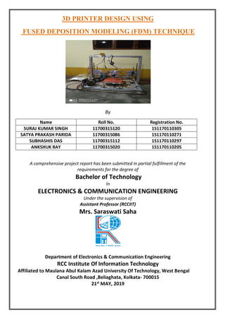
  • 1. 3D PRINTER DESIGN USING FUSED DEPOSITION MODELING (FDM) TECHNIQUE By Name Roll No. Registration No. SURAJ KUMAR SINGH 11700315120 151170110305 SATYA PRAKASH PARIDA 11700315086 151170110271 SUBHASHIS DAS 11700315112 151170110297 ANKSHUK RAY 11700315020 151170110205 A comprehensive project report has been submitted in partial fulfillment of the requirements for the degree of Bachelor of Technology In ELECTRONICS & COMMUNICATION ENGINEERING Under the supervision of Assistant Professor (RCCIIT) Mrs. Saraswati Saha Department of Electronics & Communication Engineering RCC Institute Of Information Technology Affiliated to Maulana Abul Kalam Azad University Of Technology, West Bengal Canal South Road ,Beliaghata, Kolkata- 700015 21st MAY, 2019
  • 2. CERTIFICATE OF APPROVAL This is to certify that the project titled “Design and Development of 3D Printer ” carried out by: Name Roll No. Registration No. SURAJ KUMAR SINGH 11700315120 151170110305 SATYA PRAKASH PARIDA 11700315086 151170110271 SUBHASHIS DAS 11700315112 151170110297 ANKSHUK RAY 11700315020 151170110205 for the partial fulfillment of the requirements for B.Tech degree in Electronics and Communication Engineering from Maulana Abul Kalam Azad University of Technology, West Bengal absolutely based on his own work under the supervision of Mrs. Saraswati Saha. The contents of this thesis, in full or in parts, have not been submitted to any other Institute or University for the award of any degree or diploma Optional in case of external supervisor …………………………………………… …………………………………………… Dr./Mr./Ms./Mrs. Dr./Mr./Ms./Mrs. Designation and Department Professor, Dept. of ECE Institute RCC Institute of Information Technology …………………………………………… Dr./Mr./Ms./Mrs. Head of the Department (ECE) RCC Institute of Information Technology
  • 3. DECLARATION “We Do hereby declare that this submission is our own work conformed to the norms and guidelines given in the Ethical Code of Conduct of the Institute and that, to the best of our knowledge and belief, it contains no material previously written by another neither person nor material (data, theoretical analysis, figures, and text) which has been accepted for the award of any other degree or diploma of the university or other institute of higher learning, except where due acknowledgement has been made in the text.” ……………………………… ……………………………… SURAJ KUMAR SINGH SATYA PRAKASH PARIDA (ECE2015/019) (ECE2015/020) Registration No: 151170110305 of 2015-2016 Registration No: 151170110271 of 2015-2016 Roll No: 11700315120 Roll No: 11700315086 ……………………………… ……………………………… SUBHASHIS DAS ANKSHUK RAY (ECE2015/006) (ECE2015/037) Registration No: 151170110297 of 2015-2016 Registration No: 151170110305 of 2015-2016 Roll No: 11700315112 Roll No: 11700315120
  • 4. CERTIFICATE OF ACCEPTANCE This is to certify that the project titled “Design and Development of 3D Printer ” carried out by: Name Roll No. Registration No. SURAJ KUMAR SINGH 11700315120 151170110305 SATYA PRAKASH PARIDA 11700315086 151170110271 SUBHASHIS DAS 11700315112 151170110297 ANKSHUK RAY 11700315020 151170110205 is hereby recommended to be accepted for the partial fulfillment of the requirements for B.Tech degree in Electronics & Communication Engineering from Maulana Abul Kalam Azad University of Technology, West Bengal Name of the Examiner Signature With Date 1 . …………………………………………………………………………………… 2 . …………………………………………………………………………………… 3 . …………………………………………………………………………………… 4 . ……………………………………………………………………………………
  • 5. CONTENTS TOP PAGE……..……………………………………………………………..1 CERTIFICATE……………………………………………………………….2 DECLARATION……………………………………………………………..3 CERTIFICATE OF ACCEPTANCE…………………………………………4 CONTENTS…………………………………………………………………..5 ABSTRACT…………………………………………………………………..7 LIST OF COMPONENTS USED…………………………………………….8 LIST OF ABBREVIATIONS………………………………………………...9 LIST OF FIGURES………………………………………………………….10 LIST OF TABLES…………………………………………………………...11 1. INTRODUCTION…………………………………………………….12 2. PROJECT REPORT AT A GLANCE………………………………...12 2.1 Definition………………………………………………………….13 2.2 Design……………………………………………………………..14 2.3 Problem Statement………………………………………………...14 2.4 Possible Solution…………………………………………………..14 2.5 Simplified Block Diagram………………………………………....15 2.6 Working With Files………………………………………………..16 2.7 How 3D Printer Works…………………………………………….17 3. COMPONENTS DESCRIPTION……………………………………..17 3.1 Frame………………………………………………………………17 3.2 Extruder……………………………………………………………18 3.3 Stepper Motor……………………………………………………...19 3.4 A4988 Motor Driver……………………………………………….20 3.5 Plastics……………………………………………………………..21 3.5.1 Polylactic acid plastics………………………………………21 3.6 Software Needs To install………………………………………….22 3.6.1 Arduino Software...………………………………………….22 3.6.2 Sli3r software………………………………………………..22 3.6.3 Proterface software…………………………………………..22 3.7 Basic electronic connections……………………………………….22 3.8 FrameWork...………………………………………………………23 4. PRESENT 3D PRINTING TECHNOLOGY………………………….24
  • 6. 4.1 Fused Deposition Modeling(FDM)……………………………….25 4.2 Selective Laser Melting(SLM)………………………………….....26 5. WORKING OF THE DEVICE……………………………………….26 6. FINAL RESULTS....…………………………………………………..33 7. FUTURE SCOPE AND APPLICATONS…………………………….35 8. CONCLUSION………………………………………………………..36
  • 7. ABSTRACT Nowadays 3D printing has become a big boom. This technology is not only used in industries but also used at those places where the prototyping is an important constraint .This project aims to develop a 3D printer that not only counts for a cost effective output but a product that can be used by each and every one. After this project gets a final touch it will benefit the common people where the cost effectiveness is very crucial. Many 3D printing technologies are available to build a 3D object but this project aims to use that 3Dmanufacturing process that gives a cost effectiveness solution at a low wastage of printing material.3D printers capable of outputting in color and multiple materials already exist and will continue to improve to a point where functional products will be able to be output. Printing rather than “3D printing” has bought a radical change in the world we live. Now a days 3D-Printing has gone from developing a factory need object to a medical need artificial bones and making it a “low cost” is the new area of development. Gone are those days where the 3D objects were brought from the market, who would have thought that this 3D printer would do the same work with a low cost!!! “Once We have this fascinating 3D printer, do not forget the fact this is a low cost one!!”
  • 8. LIST OF COMPONENTS USED NAME QUANTITY Arduino Mega with RAMPS 1.4 Controller 1 Extruder kit 0.4mm extrusion head 1 Endstops 3 A4988 stepper motor driver 4 PLA & ABS filaments 1 KG Heat bed 1 SMPS 1 UPS 1 Frame ,bearings,pulley,MK8 rods
  • 9. LIST OF ABBREVIATIONS Name Abb. PLA Poly(lactic acid) or polylactic acid or polylactide (PLA) ABS Acrylonitrile butadiene styrene - thermoplastic polymer SMPS switched-mode power supply
  • 10. LIST OF FIGURES Figure 1 Ideal Nozzle Placement Figure 2 Block Diagram of the Entire System Figure 3 STL File Figure 4 Frame Figure 5 Extruder Figure 6 Stepper Motor Figure 7 Driver A4988 Figure 8 Simplified connection of Driver and controller Figure 9 ABS Plastic Figure 10 PLA Plastic Figure 11 SMPS Figure 12 A4988 Driver Figure 13 A4988 Driver heat sink Figure 14 Arduino ATMega 2560 Figure 15 Connection of Arduino 2560 and Ramp 1.4D Figure 16 Running motors through electronics Figure 17 FrameWork Figure 18 Fused Deposition Method Figure 19 SLM Figure 20 Slicing Procedure Figure 21 Pronterface action Figure 22 Endstop position Figure 23 Final Results
  • 11. History of printing starts from the duplication of images by means of stamps followed by the flat bed printing process in 18th century. In mid of the 19th centuries color printing called as Chromolithography became very popular. A revolution occurred when the print workings, specifically a 2D printer was used as a peripheral device, which made a persistent human readable representation of the graphics a text in paper. After some years the concept of 3D printer starts evolving, a new way to look at the past printing technologies. Our report emphasizes on the design and development of a low-cost 3D printer. 3D printer basically is concept to make or print the objects layer by layer and thus making it so called “Three dimensional”. Nowadays 3D printer available is of higher costs that is due to the printing technology used and the material used in 3D printer, so this project sparks upon making the 3D printer low cost by using the scrap materials and designing a frame for the 3D printer. The main aim of this project is to make the 3D printer available to a common man making this equipment easy to operate and automate working once the command and specific design is given to this device. So operating time will automatically decrease as it can handle the task without any human intervention. This also makes this device reasonable and approachable to everyone this project. This project deals or in other words targets the people who has cost as a main constrain and thus making a 3D printer useful in school laboratories, making imitation jewelry for women, automobile industries, making a prototype material in industries etc. This chapter deals with the introduction, design and goal and the basic working principle of how the project works with a simplified block diagram and its brief explanation. Thus, with this chapter the main motive of the project would be clear with the basic understanding of the project. 1. INTRODUCTION 2.PROJECT REPORT AT A GLANCE
  • 12. 2.1 Definition 3D Printing technology is an additive manufacturing technology where a three-dimensional object is created. This technology is a rapid prototyping technology. 2.2 Design The design structure that this project aims is a FDM Model. 2.3 Problem Statement The present 3D printing technology is very time consuming with a high manufacturing cost. This project aims not only to reduce the cost of the 3D Printer but also working upon its accuracy and time constraints. 2.4 Possible Solution The possible solution is designing a frame and using only the most important materials and using the printing technology that minimizes the wastage of plastic to give maximum efficiency to the product output. FIGURE 1
  • 13. 2.5 Simplified Block Diagram FIGURE2.BLOCK DIAGRAM OF THE ENTIRE SYSTEM This above block diagram describes the basic working of the product. As shown in above block diagram: Firstly, a 3D object is designed using a CAD Tool and then is converted in such a file format specifically a G-Code using software’s like FDM that is understandable by the electronics that mainly includes the Microcontroller. Input is given to the electronics that give commands to the motors according to the design in the CAD Tool. The mechanical components including motors, extruder works accordingly and thus a layer by layer object is printed (in layman language plastic is glued) on the print plate or glass plate. After the 3D object gets cooled to a certain temperature the final end product can be taken out. In this way the simple process works to build a 3D object. Thus, a prototyping of the project also becomes easier as the specified or the required designed on an initial stage is formatted on a CAD Tool and your printer starts to print! To get a change in the final product structure the design in the CAD Tool only needs the change, rest all the working remains unchanged. 3D OBJECT DESIGN CONVERSION TO RELEVENT CODE INPUT TO THE PROCESSOR MECHANICAL PROCESSINGS PRINTING 3D OBJECT IS READY
  • 14. 2.6 Working with Files FIGURE3.STL FILE There are several different file types used in 3D Printing file extensions that includes. stl, .g-code, .factory. STL and OBJ files are the output from the CAD Software’s. After the STL and OBJ files are imported the next work is to add the process. This process adds all the information that how the object is sliced and printed on the print plate including the settings of the extruder, infill, temperature, supports etc. After this process is saved and exported an FFF file is created. If we want to again change the process settings for example changing the printing speed, infill percentage etc. There comes option of “Edit Process Settings”. After making such modification the OK option is clicked to save the changes .G-Code / X3G files gives the instructions for the printer. G-code tells the machines how much to move, where to move, how fast to move. Such types of settings are also called as 3D Printing Tool Path. G-code uses plain text format while the X3G uses binary language which is used by the machine with the maker boat type firm wares. When the option Prepare to Print is clicked the3D model will automatically get converted into 3D Tool paths for the machine. Factory files is a combined file to retain the simplify 3D Project. It offers a unique way to save all the data about the project into a comprehensive file called as “Factory File”. This file includes copy of 3D models been imported, their positions on bed, process settings etc. 3D Printers typically uses software that “slices” a 3D model into layers and then the software generates a G-Code that extrudes the plastic to fill each layer. Mostly slicer software works, CAD program is compatible of producing STL’s.
  • 15. 2.7 How 3D Printer Works? The basic working principle of 3D printer is to print the object layer by layer fill the targeted object design and to finish the printer has a frame structure and three axis x y and z axis that moves left to right front to back and up and down. The component called extruder which is responsible for feeding the plastic to print and melt the plastic. To print the plastic layer the movement of the extruder and stepper motor need to be controlled for that PWM generated by the Arduino is used, the g-code generated is used to drive the axis accordingly with help of CAD tools targeted objects are designed and converted into g- codes with the help of software like FDM and being given to electronics that includes motor which is placed on the frame according to the frame design. According to the commands given to the electronics motor works and through the help of extruder which is also running through the motor melts the plastic accordingly on the print plate. The plastic material used in this project is bio degradable plastic materials. After the object is finished the final object is taken out. In this way the process started with the designing object specifically a 3D object and ended with the generating the same 3D object same object in front our eyes! This chapter includes the description of various different components used in the development of the system project. It is really very necessary to describe the features of the components that are used in the designing of the system. This chapter includes the brief description of the components along with their pin configuration and different features. 3.1 Frame Selection of frame is an essential part for system designing. This frame gives the support to the printer. All the axes of the motor added to this frame. The threaded rods are mounted on this frame and rubber strips controlled by motor action. 3.Component Description
  • 16. FIGURE4. FRAME 3.2 Extruder FIGURE5. EXTRUDER Extruder consists of two parts, a cold top part that feeds the plastic filament, hot part at bottom that melts and extrudes the plastic. The speed of the
  • 17. extruder head may also be controlled, to stop and start deposition and form and interrupted plane without stringing or drabbing between sections. 3.3 Stepper Motor The stepper motor is an electromagnetic device that converts digital pulses into mechanical shaft rotation. Many advantages are achieved using this kind of motors, such as higher Simplicity, since no brushes or contacts are present, low cost, high reliability, high torque at low speeds, and high accuracy of motion. This project involves the usage of at least five motors specifically five stepper motors .one motor to control the Y-axis, the other to control the X-axis, two to control Z-axis and one to control the extruder. The configuration of all the five motors is same and the driver is used to drive the motor. FIGURE6. STEPPER MOTOR The two types of stepper motors that are the bipolar motor and unipolar motor. The bipolar and unipolar motors are similar, except that the Unipolar has a center tap on each winding.
  • 18. 3.4 Driver A4988 FIGURE7. DRIVER A4988 The driver features adjustable current limiting, over current protection, and five different micro step resolutions. It operates from 8 – 35 V and can deliver up to 2 A per coil. Five drivers are used for running 5 motors. Heat bed is pasted on the ramp so that IC should not be burned out. Things to remember:  To place the driver on Ramp 1.4 in a way that the pins of the driver should not bent.  To look whether the Ramp IC is burning.  Heat bed to be attached on each driver. FIGURE8. Simplified connection of Driver and controller
  • 19. 3.5 Plastics Plastics are one of the most important materials that are required because it is the material of which the end product is made. This project uses two types of plastics. 3.5.1 Polylactic Acid or Polylactide (PLA) Plastics It is a biodegradable plastic material which is made from renewable resources such as corn starch and sugarcane. The main difference between the two plastics is that the ABS plastic type is known for its toughness whereas the other is known for its soft type of material. Thus, for different purpose different plastic materials are used. Figure 9 ABS Plastic Figure Figure10 PLA Plastic 3.6 The Software That Needs to Be Installed on the Computer to Run the Model: 3.6.1 Arduino Software: This application allows installing the printer firmware on the ATMEGA 2560 microprocessor. To update the firmware each time this installation is required. 3.6.2 SLIC3R Software: The application to slice STL files into the G-Code is called as Skein Software. Each time the part that needs to be printed needs this type of software. 3.6.3 PRONTERFACE Software: Before the print job this application is responsible for the communication with the electronics. In simple words it makes the printing output to be ready before the actual printing job. 3.7 TO DO LIST: Basic electronics connection:
  • 20. Step 1: Look for an appropriate power source that will give the circuit 12V. For safety we should SMPS. FIGURE11. SMPS Step 2: Paste heat sink on the drivers as shown below so that the IC would not get damaged. Figure 12 A4988 Driver Figure 13 A4988 Driver Step 3: Take Arduino 2560 and Ramp 1.4 male and connect it as shown.
  • 21. FIGURE14. Arduino Atmega 2560 Step 4: Attach all the 5 drivers on the Ramp 1.4 as shown below and connect all the stepper Motor’s to the drivers. 3.8 Framework After assembling the whole electronics part now, it is the time for the mechanical structure to be decided and to fit our electronics in it.  Decide the frame structure.  Assemble the structure using rods or waveguide structure and integrate electronics in it. Figure 15 Connection of Arduino 2560 Ramp 1.4D Figure 16 Running motors through electronics
  • 22. FIGURE17.FRAMEWORK The aim of all the 3D printing technologies is to develop an additive manufacturing process that creates an object layer by layer. Some common features for all the additive manufacturing processes is the usage of computer with special 3D modeling software. The first part of this process is to create a CAD diagram. The AM device reads the output from the CAD file and builds a structure layer by layer with the printing material which can be plastic, powder filaments or may be a sheet of paper. This chapter deals with all the famous 3D Printing Technologies that are used commonly. 4.1 Fused Deposition Modeling (FDM) Fused Deposition Modeling (FDM) technology was developed and implemented in 1980’s. By using this method not only functional prototypes can be printed but also concept models and final end-use product is implemented. What is good about this technology is that all parts printed with FDM can go high-performance which is highly beneficial for mechanic engineers and manufactures. FDM is the only 3D printing technology that builds parts with production grade thermoplastics, so things printed are of excellent mechanical, thermal and chemical qualities. This method does not waste plastics so this method is widely used more over this method does not uses lasers. 4. Present 3D Printing Technologies
  • 23. 3D printing machines that use FDM Technology build objects layer by layer from the very bottom up by heating and extruding thermoplastic filament. The whole process is bit similar to stereo lithography .Firstly a special software “cuts” CAD model into layers and calculates the way printer’s extruder would build each layer then the printer heats thermoplastic till its melting point and extrudes it throughout nozzle onto base, that can also be called a build platform or table along the calculates path. Once the layer is finished, the base is lowered to start building of next layer. Compared to the previous process this method is bit slower. When printing is completed support materials can easily be removed by placing an object into water and a detergent solution. FIGURE18.Fused Deposition Method 4.4 Selective Laser Melting (SLM) Selective laser melting (SLM) is a technique that also used 3D CAD data as a source and forms a3D object by means so a high-power laser beam that fuses and melts metallic powders together. This method fully melts the metal material into solid 3D- dimensional part unlike selective laser sintering. The fine metal powder is evenly distributed onto a plate, and then each slice of 2Dlayer image is intensively fused by applying high laser energy that is directed to the powdered plate. The energy of laser is so intense that the metal powder melts fully and forms a solid object. After the layer is completed the process starts over again for the next layer. Metals that can be used for SLM include stainless steel, titanium, cobalt chrome and aluminum.
  • 24. FIGURE 19.SLM 5. Working of the Device Once the STL file ready, it is sliced in Slicer or in Cura or may be in any other slicing software. Slicing is the process of conversion of the STL file to .gcode format. This includes the process of deciding the nozzle movements in space in order to make the design. Several settings are made in this section of the print by engineers in order to achieve the best quality print. Each printer has its own slicer settings. Everything, starting from the melting temperature of the PLA material to setting of the bed temperature is done here. The layer width is the most crucial portion of any 3d print Sets of data are prepared and print quality is judged. The figure below shows the whole process in a nutshell: Figure 20. Slicing Procedure
  • 25. For our 3D printer the specifications are mentioned below: CURA: Profile Fine Layer Height 0.1mm Initial Layer Height 0.3mm Line width 0.4mm wall line width 0.4mm outer wall line width 0.4mm inner wall line width 0.4mm to/bottom line width 0.4mm infill line width 0.4mm skirt/bottom line width 0.4mm support line width 0.4mm initial layer line width 100.0% wall thickness 0.8mm wall line count 2 to 5 outer wall wipe distance 0.2mm top surface skin layers 0 top/bottom Thickness 0.8mm top layers 8 bottom thickness 0.8mm bottom layers 8 top/bottom patterns lines(changeable) bottom pattern initial layer lines(changeable) top/bottom line directions [] outer wall inset 0mm optimize wall printing order no outer before inner walls no alternate extra wall no compensate wall overlaps yes compensate outer wall overlaps yes minimum wall flow 0% fill gaps between walls everywhere filter out tiny gaps no print thin walls yes horizontal expansion 0mm initial layer horizontal expansion 0mm Z seam alignment sharpest corner seam corner preference hide seam ignore small Z gaps no
  • 26. extra skin wall count 1 enable ironing no infill density 20%(adjustable) infill line distance 4.0mm infill pattern grid(changeable) connect infill lines no infill line directions [] infil X offset 0mm infill Y offset 0mm infill line multiplier 1 extra infill wall count 0 infill overlap percentage 10% infill overlap 0.04mm skin Overlap 5% infill wipe distance 0.1mm infill layer thickness 0.1mm Gradual Infill steps 0 infill before walls yes minimum infill area 0 mm2 infill support no skin removal width 0.8mm skin expand distance 0.8mm maximum skin angle for expansion 90 minimum skin width for expansion 0 default printing temperature 212deg c printing temperature 212deg C flow 100% enable retraction yes retract at layer change yes retraction distance 6.5mm retraction speed 25mm/s retraction extra prime amount 0 retraction minimum travel 0.8mm maximum retraction count 90 maximum extrusion distance window 6.5mm limit support retractions yes nozzle switch retraction speed 20mm/s Print speed 60mm/s infill speed 60mm/s wall speed 30mm/s inner wall speed 60mm/s outer wall speed 30mm/s
  • 27. top/bottom speed 30mm/s support speed 60mm/s support infill speed 60mm/s travel speed 130mm/s initial layer speed 30mm/s initial layer print speed 30mm/s initial layer travel speed 60mm/s skirt/brim speed 30mm/s maximum Z speed 0mm/s number of slower layers 2 equalize filament flow no enable acceleration control no enable jerk control no combing mode all max comb distance 0 retract before outer wall no avoid printed parts when travelling yes avoid supports while travelling no travel avoid distance 0.625 mm generate support material yes support material placement everywhere overhang angle 50deg support pattern zigzag support density 15% build plate adhesion skirt skirt line count 1 print sequence all at once The Slicing is then done which creates the G-code. After g-code is prepared the printer is fed with the g-code with the help of Pronterface/Cura to print the 3d model. Figure 21. Pronterface action
  • 28. The ramps is connected to Arduino which is fed with the Marlin code required to decode the g-code to microprocessor commands. Marlin source code is open source Arduino code available for the printers. Once the printer is made the engineers calibrate the code and change it accordingly in order to produce the best results. Following are some snaps from our revised marlin code.
  • 29. How Marlin Works The Marlin syncs the motor movements and the actual length or distance moved by the nozzle to that required. Marlin Firmware runs on the 3D printer’s main board, managing all the real- time activities of the machine. It coordinates the heaters, steppers, sensors, lights, LCD display, buttons, and everything else involved in the 3D printing process. Marlin implements an additive manufacturing process called Fused Deposition Modeling (FDM) — aka Fused Filament Fabrication (FFF). In this process a motor pushes plastic filament through a hot nozzle that melts and extrudes the material while the nozzle is moved under computer control. After several minutes (or many hours) of laying down thin layers of plastic, the result is a physical object. The control-language for Marlin is a derivative of G-code. G-code commands tell a machine to do simple things like “set heater 1 to 180°,” or “move to XY at speed F.” To print a model with Marlin, it must be converted to G-code using a program called a “slicer.” Since every printer is different, you won’t find G-code files for download; you’ll need to slice them yourself. As Marlin receives movement commands it adds them to a movement queue to be executed in the order received. The “stepper interrupt” processes the queue, converting linear movements into precisely-timed electronic pulses to the stepper motors. Even at modest speeds Marlin needs to generate thousands of stepper pulses every second. (e.g., 80 steps-per-mm * 50mm/s = 4000 steps-per-second!) Since CPU speed limits how fast the machine can move, we’re always looking for new ways to optimize the stepper interrupt! Heaters and sensors are managed in a second interrupt that executes at much slower speed, while the main loop handles command processing, updating the
  • 30. display, and controller events. For safety reasons, Marlin will actually reboot if the CPU gets too overloaded to read the sensors. The part of the code responsible for that is shown below: "Jerk" specifies the minimum speed change that requires acceleration. When changing speed and direction, if the difference is less than the value set here, it may happen instantaneously. Software Endstops: The machine starts and hence checks the boundaries according to the code. This calls for the requirement of end stops. The end stops are needed for the following: - Prevent moves outside the set machine bounds. - Individual axes can be disabled, if desired. - X and Y only apply to Cartesian robots. The figure below shows the end-stops fixed on the machine:
  • 31. The code portion required is: After the boundaries are checked printer starts to print the model layer-wise a block diagram below shows the whole process in a nutshell.
  • 32. Figure 21. Process in nutshell-1 Figure 22. Process in nutshell-2
  • 33. FINAL RESULTS: 1.The 3D Printer: 2. Orthodontic appliance, temporary teeth and Daily Used Products – Mobile Cover, Utensils, Vase Etc
  • 34. 3.Building structures ,spare parts and artifacts and many more.
  • 35. Future Scope and Applications: • 40 % of 3D printing patent applications are medical. A Process called bio texture modeling allows us to print stimulated organs with texture & wetness of real things. • • 3D Scans of patients can help create custom built prosthetic and face prosthetics • Customized bone replacements can be executed 3D printing. • Orthodontic appliances, temporary teeth, dental crowns can be 3D printed. • Bio printing is the process of printing out organic tissue which could facilitate organ transplants.
  • 36. Conclusion:  We get high precision regardless of uneven heating or bowed build plate.  Sensors ensure the print head is always moving parallel to the build plate.  No wasting time fiddling with the bed and Z height. It’s easy of for inexperienced machinists to use it .  Use of filament effective reduces the wasting of filaments.  Hence we are intended to produce a low cost 3D printer for all with an estimated cost of 11000 INR.
  • 37. References 1.3D Printing for Model Engineers A Practical Guide Neil Wyatt 2.3D Printing Failures 2019 Edition: How to Diagnose and Repair ALL Desktop 3D Printing Issues Sean Aranda 3.Cutting-Edge 3D Printing Karen Latchana Kenney 4.Fusion 360 for Makers Design Your Own Digital Models for 3D Printing and CNC Fabrication Lydia Sloan Cline