1. How to Design a Geometric Stained Glass Lamp Shade
This technique requires no calculation tables, math, or angle computation. Instead you can use paper & pencil
with basic tech drawing skills to design any size or shape spherical lamp with any number of panel sides and
any number of layers or tiers.
Gather the following supplies:
1. 11 x 17 or A3 size paper
2. Sharp, hard lead pencils
3. A standard ruler (a set of parallel rules is also helpful)
4. A T-square
5. A 45
triangle
6. Protractor
7. Compass
°
Set Your Scale
Using one centimeter on the drawing = one inch on the finished shade works well. This way you get a drawing
of decent size on the paper that easily converts to the finished size templates you will create to make the lamp.
Design Your Shade
1. Layout a clean sheet of paper oriented landscape
(long edges hor izontal) and tape onto a good
square edge drawing or drafting surface.
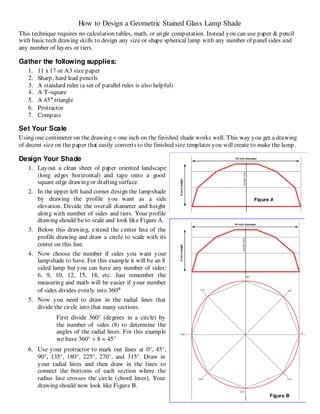
2. In the upper left hand corner design the lampshade
by drawing the profile you want as a side
elevation. Decide the overall diameter and height
along with number of sides and tiers. Your profile
drawing should be to scale and look like Figure A.
3. Below this drawing, extend the center line of the
profile drawing and draw a circle to scale with its
center on this line.
4. Now choose the number if sides you want your
lampshade to have. For this example it will be an 8
sided lamp but you can have any number of sides:
6, 9, 10, 12, 15, 18, etc. Just remember the
measuring and math will be easier if your number
of sides divides evenly into 360
°
5. Now you need to draw in the radial lines that
divide the circle into that many sections.
First divide 360° (degrees in a circle) by
the number of sides (8) to determine the
angles of the radial lines. For this example
we have 360° ÷ 8 = 45°
6. Use your protractor to mark out lines at 0°, 45°,
90°, 135°, 180°, 225°, 270°, and 315°. Draw in
your radial lines and then draw in the lines to
connect the bottoms of each section where the
radius line crosses the circle (chord lines). Your
drawing should now look like Figure B.
Figure A
Figure B
2. How to Design a Geometric Stained Glass Lamp Shade
7. Now draw vertical lines from the side elevation
drawing from where each layer meets down to
the horizontal line on the right side of the full
circle drawing (blue lines on Figure C).
8. Each blue vertical line that passes through our
horizontal (0
°
) line now defines the radius of an
arc to draw that passes through the horizontal
line and the radial section line just above it (the
45
line here). Use a compass with the point set
at the circle center and draw in the arc for each
vertical line. Leave the compass set the final
arc’s radius for the next step. This will become
our working section. The drawing should now
look Figure C.
9. Now you need to draw an angle bi-sect of the
working section. This is a line that will divide
the angle of our working section into two equal
angles.
a. Using the compass still set from the last
arc created in step 8, put the compass
point where the second arc meets our 0
°
line and draw a small arc out past the
circle and near what looks like the
middle of our section. (Green line in Figure D).
Figure C
b. Without changing the compass angle, put the point where that same second arc meets the 45
degree line and make a small arc that intersects the first one.
c. Now draw a line that connects the center point of our circle and extends through this intersection
° point and extends way out into the empty right side of our paper. The drawing should now look
like Figure D.
Figure D
3. How to Design a Geometric Stained Glass Lamp Shade
10. Next draw lines parallel to the angle bisection line from each point where an arc and the lamp diameter
circle line meets either angle line that defines the working section, here it is the 0 and 45 lines. (This is
where a set of parallel rules can come in handy). These lines will create the widths for your templates.
The drawing now looks like Figure E.
Figure E
Figure E
11. Next draw a line perpendicular to this group of parallel lines. With your compass measure the length of
the profile line on the lowest tier. Without changing the compass, place the point where the
perpendicular line meets the outer most parallel line (a) and then strike a small arc that crosses through
the next parallel line just inside (b). Repeat from the opposite side, placing the point of the compass at A
and striking the arc on line B. Draw lines (purple) to connect points a-A and b-B then complete the
shape by drawing another perpendicular line connecting A to B. This is the shape, to scale that makes up
the bottom tier of your lamp. See Figure F.
Figure F
4. How to Design a Geometric Stained Glass Lamp Shade
12. Duplicate the process in step 11 for each tier of your lamp until all shapes are drawn. Your drawing will
now look like this:
13. The last step is to create true size templates for each
tier. Measure accurately (in centimeters) the lengths
and widths you have for each tier layer. Convert the
measurement to inches (remember our scale 1 cm =
1 inch) and then precisely draw out these shapes.
Using a gridded paper that has been glued to a light
cardboard will make this easier and make nice final
templates for cutting your glass
14. Each tier template can be used as a space to design
additional detail into your lamp. For example let’s
say you want to put a flower design into each piece
that makes up the middle tier. Using that template to
define the space for your design. Create a pattern, cut, foil, and then
assemble the design, making the same number of copies as the number of
sections in your lamp (in our example this is 8). If you use layout blocks to
define the template boundaries and assemble your design inside it will be
easier to make sure your final sections stay consistent to each other and to
the shape and size that makes up the tier. Keep in mind that the more
complex the pattern, the more diff icult it will be to maintain a uniform size.
Other options include modifying the lower edge of the bottom tier giving it
a scallop shape instead of straight across.
15. Now you can design any regular geometric style stained glass shade with
the shape, size, and number of tiers you want!
16. And in case you’re interested, the final drawing would look like this:
Figure G
Figure H
Figure H
5. How to Design a Geometric Stained Glass Lamp Shade
This how to technique is based in the information found on the Karal Studios website