PLC Counters
•
0 gefällt mir•3,263 views

plc, PLC Applications, Programmable Logic Controllers, Programmable, Logic, Controllers, PROGRAMMING, gates, COUNTERS, Timers,LOGIC CIRCUITS, INTERNAL RELAYS, ARITHMETIC FUNCTIONS, Application, Data Types and Addressing,

Empfohlen
Weitere ähnliche Inhalte
Was ist angesagt?
Was ist angesagt? (20)
Andere mochten auch
Andere mochten auch (20)
Ähnlich wie PLC Counters
Ähnlich wie PLC Counters (20)
Mehr von Ameen San
Kürzlich hochgeladen
Kürzlich hochgeladen (20)
PLC Counters
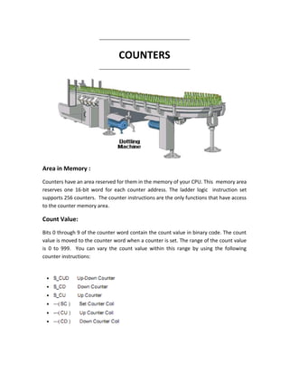
- 1. ___________________________________ COUNTERS ___________________________________ Area in Memory : Counters have an area reserved for them in the memory of your CPU. This memory area reserves one 16-bit word for each counter address. The ladder logic instruction set supports 256 counters. The counter instructions are the only functions that have access to the counter memory area. Count Value: Bits 0 through 9 of the counter word contain the count value in binary code. The count value is moved to the counter word when a counter is set. The range of the count value is 0 to 999. You can vary the count value within this range by using the following counter instructions:
- 2. If I0.1 changes from "0" to "1", the counter is preset with the value at PV (10 in the above figure). If the signal state of I0.0 changes from "0" to "1", the value of counter C10 will be incremented by one - unless the value of C10 is equal to "999". Q4.0 is "1" if C10 is not equal to zero. If I0.1 changes from "0" to "1", the counter is preset with the value at PV (20 in the above figure). If the signal state of I0.0 changes from "0" to "1", the value of counter C10 will be decremented by one - unless the value of C10 is equal to "0". Q4.0 is "1" if C10 is not equal to zero.
- 3. If I0.2 changes from "0" to "1", the counter is preset with the value at PV (20 in the above figure). If the signal state of I0.0 changes from "0" to "1", the value of counter C10 will be incremented by one - except when the value of C10 is equal than "999". If I0.1 changes from "0" to "1", C10 is decremented by one - except when the value of C10 is equal to "0". Q4.0 is "1" if C10 is not equal to zero.
- 4. If the signal state of input I0.0 changes from "0" to "1" (positive edge in RLO), the preset value of 100 is loaded to counter C10. If the signal state of input I0.1 changes from "0" to "1" (positive edge in RLO), counter C10 count value will be incremented by one unless the value of C10 is equal to "999". If there is no positive edge in RLO, the value of C10 will be unchanged. If the signal state of I0.2 is "1", the counter C10 is reset to "0".
- 5. If the signal state of input I0.0 changes from "0" to "1" (positive edge in RLO), the present value of 100 is loaded to counter C10. If the signal state of input I0.1 changes from "0" to "1" (positive edge in RLO), counter C10 count value will be decremented by one unless the value of C10 is equal to "0". If there is no positive edge in RLO, the value of C10 will be unchanged. If the count value = 0, then Q4.0 is turned on. If the signal state of input I0.2 is "1", the counter C10 is reset to "0".