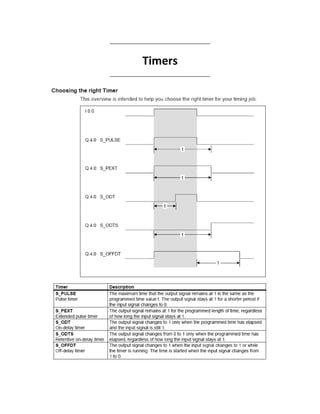
PLC Timers
•
1 gefällt mir•1,500 views

plc, PLC Applications, Programmable Logic Controllers, Programmable, Logic, Controllers, PROGRAMMING, gates, COUNTERS, Timers,LOGIC CIRCUITS, INTERNAL RELAYS, ARITHMETIC FUNCTIONS, Application, Data Types and Addressing,

Empfohlen
Weitere ähnliche Inhalte
Was ist angesagt?
Was ist angesagt? (20)
Ähnlich wie PLC Timers
Ähnlich wie PLC Timers (20)
Mehr von Ameen San
Mehr von Ameen San (20)
Kürzlich hochgeladen
Kürzlich hochgeladen (20)
PLC Timers
- 7. Applications 01: For the starter control shown below, when the start button S1 is pressed, the line contactor K1 is energized. Contactors K4, K3 and K2 are then energized with a delay of 5 seconds between each to short-circuit their relevant resistor groups. When the last contactor K2, has energized, the slip rings of the armature are short circuited and the motor runs at its rated values. By pressing the stop button S0 or when the protection fuse is tripped, the control is stopped.
- 8. Ladder Diagram STL A "Start" S M 0.0 A( O "Stop" O "Fuse" ) R M 0.0 NOP 0 A M 0.0 AN "K2" AN "K3" AN "K4" S "K1" AN M 0.0 R "K1" NOP 0 A T 4 S "K4" A( O "K3" ON M 0.0 ) R "K4" NOP 0 A T 3 S "K3" A( O "K2" ON M 0.0 ) R "K3" NOP 0
- 9. A T 2 S "K2" AN M 0.0 R "K2" NOP 0 A M 0.0 L S5T#5S SS T 4 A( ON M 0.0 O "K3" ) R T 4 NOP 0 NOP 0 NOP 0 A M 0.0 L S5T#10S SS T 3 A( ON M 0.0 O "K2" ) R T 3 NOP 0 NOP 0 NOP 0 A M 0.0 L S5T#15S SS T 2 AN M 0.0 R T 2 NOP 0 NOP 0 NOP 0
- 10. FBD
- 12. Applications 02: Design a ladder program to solve the following control problem: For the shown liquid level control, when the start button is pressed, the inlet valve is opened until receiving a high signal from the level switch. After filling the tank the motor runs for 10 seconds. Then, the outlet valve is opened until receiving a low signal from the level switch. The filling process is restarted automatically. The stop button ends the process. Ladder STL A I 0.0 S M 0.0 A I 0.1 R M 0.0 NOP 0 A M 0.0 AN I 0.2 S Q 4.0 A( ON M 0.0 O Q 5.0 O I 0.2 ) R Q 4.0 NOP 0
- 13. A M 0.0 A I 0.2 L S5T#10S SE T 1 AN M 0.0 R T 1 NOP 0 NOP 0 A T 1 = Q 4.1 A M 0.0 A I 0.2 AN T 1 S Q 5.0 A( O I 0.3 ON M 0.0 ) R Q 5.0 NOP 0