SlideShare ist ein Scribd-Unternehmen logo
1 von 67
Downloaden Sie, um offline zu lesen
Model and Texture a Photorealistic USB Cable with Maya and Mental Ray: Part 1 
In this tutorial you will go through the process of modeling and rendering a Photorealistic USB cable in Autodesk Maya. You will also learn to use Mental Ray, along with the new architectural materials, rendering layers, and Photoshop, to create a fast, accurate, and photorealistic depth of field. This is part 1 of the tutorial: the modeling process. 
Step 1 
Create a primitive cube and scale it to match the size of a USB.
Step 2 
Under the “Polygons” menu, go to the “Edit Mesh > Insert Edge Loop Tool". 
Step 3 
Create 2 edge loops.
Step 4 Select 8 vertexes from the end of the geometry, and with the scale and move tools, modify the geometry to match the basic shape of a USB. Step 5 This is how it should look (depending on the type of USB cable you are trying model).
Step 6 Select the front face of the USB.
Step 7 With that same face still selected, go to “Edit Mesh > Extrude”, and create an inner face.
Step 8 Once again, go to “Edit Mesh > Extrude”, and extrude the face inward a bit.
Step 9 Go to “Edit Mesh > Insert Edge Loop Tool", and add some edges, to create a new face on the top of the USB.
Step 10 Select the new face, then go to “Edit Mesh > Extrude”, and extrude the face slightly inward.
Step 11 Go to “Edit Mesh > Insert Edge Loop Tool”, and create 16 edges on the side of the USB.
Step 12 Select 16 faces from the 32 you just created (every other one).
Step 13 With those faces selected, go to “Edit Mesh > Extrude”, and extrude the faces inward as shown.
Step 14 Scale the shape of the faces to make them smaller on the vertical axis.
Step 15 This is how it should look on both sides.
Step 16 Go to “Edit Mesh > Insert Edge Loop Tool”, and create 2 edges on the sides of the USB. If you get a problem like the one in the image, just go to the next step.
Step 17 Go to “Edit Mesh > Split Polygon Tool”, click on the beginning of the line you want to create, and once again at the end. Do this for both edges, and for both sides of the USB.
Step 18 Select all of the small faces that you just created on the sides of the USB, then go to “Edit Mesh > Extrude”, and extrude those faces inward.
Step 19 You should have something that looks like this.
Step 20 Go to “Edit Mesh > Split Polygon Tool”, and to “Edit Mesh > Insert Edge Loop Tool”. Using both tools as necessary, create edges at every hard angle change of the USB (use the images as reference).
Step 21 When you are finished, select the USB object and simply press number 3 on your keyboard to smooth it. Then just sit back and watch how nice the smoothed USB looks.
Step 22 Now, create a primitive cube, position it, and scale it to fit inside the USB.
Step 23 Go to “Edit Mesh > Extrude”, and extrude the front face of the metal connector.
Step 24 Once again, go to “Edit Mesh > Extrude”, and extrude the face inward.
Step 25 Go to “Edit Mesh > Insert Edge Loop tool”, and create 2 edge loops through the middle of metal connector.
Step 26 Select the small faces you just created, then go to “Edit Mesh > Extrude”, and extrude them slightly inward.
Step 27 Go to “Edit Mesh > Insert Edge Loop tool”, and create some new edges to make 2 faces at the top of the connector.
Step 28 Go to “Edit Mesh > Extrude”, and extrude the 2 faces inward.
Step 29 Select the 2 faces and delete them to create 2 holes.
Step 30 Now you are going to use a different method to smooth the object (this method can only be used with simple geometry). Go to “Edit Mesh > Bevel”, set the 'Width' to '0.6' (this will depend on how smooth you want the object to be, and also the size of the object). Also, set the 'Segments' to 1, the 'Offset type' to 'Fractional', the 'Offset space' to 'World', and the 'UV assignment' to 'Planar project per face'.
Step 31 Now simply press number 3, and you should see some nice edges.
Step 32 Make a primitive cube, and fit it inside the metal connector.
Step 33 Go to “Edit Mesh > Bevel”, to smooth the cube.
Step 34 Go to the “Create > EP Curve Tool”, and set the 'Curve degree' to '3 cubic' (this will create a nice curve).
Step 35 Draw the cable as shown.
Step 36 Select the control vertexes of the curve and adjust them to your liking.
Step 37 This is how my curve looks, but you can make yours any way you like.
Step 38 Make a primitive cylinder, and scale the diameter to match your cable.
Step 39 Move the cylinder to the end of the curve.
Step 40 Scale the cylinder to match the length of the cable.
Step 41 Increase the 'Subdivisions Height' to at least 300.
Step 42 Select the cylinder, press “shift”, and then select the curve (the order in which you select the objects is very important). Now, with the objects selected, go to “Animate > Motion Path > Attach to Motion Path" (in the “Animation” menu).
Step 43 Move the time line to check if the object is moving properly.
Step 44 Now we need to make the cylinder distort around the curve. So, with the cylinder selected, go to “Animate > Motion Paths > Flow Path Object”.
Step 45 With the deformer you just created selected, change the 'T Divisions' to '400', and the cylinder should be following the curve smoothly.
Step 46 To hide the deformers, go to “Show > Deformers” in the little menu on top of perspective view.
Step 47 Now create a primitive plane for the floor.
Step 48 To attach the cable to the USB, just create a primitive cylinder, and position it as shown.
Step 49 In the “Polygons” menu, go to “Edit Mesh > Insert Edge Loop Tool”, and make some edges around the cylinder.
Step 50 Select the faces that you want to extrude, then go to “Edit Mesh > Extrude”, and extrude them inward.
Step 51 Create a primitive cylinder (this will be the thick portion of the cable).
Step 52 Change the “Subdivisions Axis” to '50'.
Step 53 Go to “Edit Mesh > Insert Edge Loop Tool”, and insert to 4 edges (2 on each side).
Step 54 Select the vertexes at the end of the cylinder and scale them.
Step 55 Do the same for the opposite side.
Step 56 Go to “Edit Mesh > Insert Edge Loop tool”, and insert some edges at the hard angles of the cylinder.
Step 57 Make sure it's the same for both sides.
Step 58 Create small cylinders and position them were you want the holes to be.
Step 59 Select the 4 cylinders, and go to “Mesh > Combine”.
Step 60 Now you need to create some geometry for the holes (this is very important, because if you don´t do it, the hole could have some errors).
Step 61 Select the big cylinder, press “shift”, and then select the small cylinders. Go to “Mesh > Booleans > Difference”.
Step 62 This is how it should look (little holes without glitches). If you do get any problems, just move the edges around until they disappear.
Step 63 Now position the cylinder where you want it to be.
Step 64 Select the front faces from both sides.
Step 65 Go to “Edit Mesh > Extrude”, and extrude the faces to make a smaller circle.
Step 66 Select the new faces, go to “Edit Mesh > Extrude” and extrude them inward.
Advertisement Step 67 This is how it should look (I have hidden the floor so you can see the results better).
Step 68 For the background, I used a cloth included in a tutorial from the “Digital Tutors” series. You can check it out here: http://www.digitaltutors.com .

Weitere ähnliche Inhalte

Was ist angesagt?

Was ist angesagt? (20)

Lesson 2 interface and bike
Lesson 2 interface and bikeLesson 2 interface and bike
Lesson 2 interface and bike
 
Solid works motion_tutorial_2010
Solid works motion_tutorial_2010Solid works motion_tutorial_2010
Solid works motion_tutorial_2010
 
Lesson 10 pdf
Lesson 10 pdfLesson 10 pdf
Lesson 10 pdf
 
Lesson8
Lesson8Lesson8
Lesson8
 
Lesson6
Lesson6Lesson6
Lesson6
 
Lesson 11
Lesson 11Lesson 11
Lesson 11
 
Rhino 3D Primer
Rhino 3D PrimerRhino 3D Primer
Rhino 3D Primer
 
Catia Part06
Catia Part06Catia Part06
Catia Part06
 
Catia Part02
Catia Part02Catia Part02
Catia Part02
 
Catia Part05
Catia Part05Catia Part05
Catia Part05
 
Lesson4 designinganametag
Lesson4 designinganametagLesson4 designinganametag
Lesson4 designinganametag
 
Lesson 9
Lesson 9Lesson 9
Lesson 9
 
Sketchup basic course by Eng. Khalid A. Mter
Sketchup basic course by Eng. Khalid A. MterSketchup basic course by Eng. Khalid A. Mter
Sketchup basic course by Eng. Khalid A. Mter
 
Lesson 7 123 design
Lesson 7 123 designLesson 7 123 design
Lesson 7 123 design
 
Catia Part07
Catia Part07Catia Part07
Catia Part07
 
CADCAM
CADCAMCADCAM
CADCAM
 
Tutorial 1 - Computer Aided Design (Final Release)
Tutorial 1 - Computer Aided Design (Final Release)Tutorial 1 - Computer Aided Design (Final Release)
Tutorial 1 - Computer Aided Design (Final Release)
 
Setting up a crash simulation in LS-Dyna
Setting up a crash simulation in LS-DynaSetting up a crash simulation in LS-Dyna
Setting up a crash simulation in LS-Dyna
 
Catia Part03
Catia Part03Catia Part03
Catia Part03
 
mastercam_full
mastercam_fullmastercam_full
mastercam_full
 

Andere mochten auch (6)

3 D Modeling Demo
3 D Modeling Demo3 D Modeling Demo
3 D Modeling Demo
 
Maya modelling and animation history
Maya modelling and animation historyMaya modelling and animation history
Maya modelling and animation history
 
Autodesk maya presentation
Autodesk maya presentationAutodesk maya presentation
Autodesk maya presentation
 
3 D Maya Introduction
3 D Maya Introduction3 D Maya Introduction
3 D Maya Introduction
 
Intro to maya
Intro to mayaIntro to maya
Intro to maya
 
Texture
TextureTexture
Texture
 

Ähnlich wie Model and texture a photorealistic usb cable with maya and mental ray

Fluid Mechanics Project Assignment (Total 15)  Due Dates  .docx
Fluid Mechanics Project Assignment (Total 15)  Due Dates  .docxFluid Mechanics Project Assignment (Total 15)  Due Dates  .docx
Fluid Mechanics Project Assignment (Total 15)  Due Dates  .docxbryanwest16882
 
Autodesk Inventor mini guide upload
Autodesk Inventor mini guide uploadAutodesk Inventor mini guide upload
Autodesk Inventor mini guide uploadBolaji Oladipo
 
Intro to Inventor with MugTree
Intro to Inventor with MugTreeIntro to Inventor with MugTree
Intro to Inventor with MugTreekrysia
 
Abaqus tutorial -_3_d_solder
Abaqus tutorial -_3_d_solderAbaqus tutorial -_3_d_solder
Abaqus tutorial -_3_d_soldernghiahanh
 
Finite Element Simulation with Ansys Workbench 14
Finite Element Simulation with Ansys Workbench 14Finite Element Simulation with Ansys Workbench 14
Finite Element Simulation with Ansys Workbench 14Prem Prakash Pandey
 
Nx basics 2014 unfnished
Nx basics 2014 unfnishedNx basics 2014 unfnished
Nx basics 2014 unfnishedMiguele Davila
 
3D Scanning and Printing
3D Scanning and Printing3D Scanning and Printing
3D Scanning and PrintingVictor Freundt
 
Skillsusa university (1)
Skillsusa university (1)Skillsusa university (1)
Skillsusa university (1)Timer Ut
 
Solid works tutorial08_bearingpuller_english_08_lr
Solid works tutorial08_bearingpuller_english_08_lrSolid works tutorial08_bearingpuller_english_08_lr
Solid works tutorial08_bearingpuller_english_08_lrAkira Tamashiro
 
Using AutoDesk Inventor to create a Trinket box
Using AutoDesk Inventor to create a Trinket boxUsing AutoDesk Inventor to create a Trinket box
Using AutoDesk Inventor to create a Trinket boxkrysia
 
Buckling Frequencies for Beams in Hypermesh
Buckling Frequencies for Beams in HypermeshBuckling Frequencies for Beams in Hypermesh
Buckling Frequencies for Beams in HypermeshAkshay Mistri
 

Ähnlich wie Model and texture a photorealistic usb cable with maya and mental ray (20)

Fluid Mechanics Project Assignment (Total 15)  Due Dates  .docx
Fluid Mechanics Project Assignment (Total 15)  Due Dates  .docxFluid Mechanics Project Assignment (Total 15)  Due Dates  .docx
Fluid Mechanics Project Assignment (Total 15)  Due Dates  .docx
 
Autodesk Inventor mini guide upload
Autodesk Inventor mini guide uploadAutodesk Inventor mini guide upload
Autodesk Inventor mini guide upload
 
Intro to Inventor with MugTree
Intro to Inventor with MugTreeIntro to Inventor with MugTree
Intro to Inventor with MugTree
 
Abaqus tutorial -_3_d_solder
Abaqus tutorial -_3_d_solderAbaqus tutorial -_3_d_solder
Abaqus tutorial -_3_d_solder
 
FEA
FEA FEA
FEA
 
Finite Element Simulation with Ansys Workbench 14
Finite Element Simulation with Ansys Workbench 14Finite Element Simulation with Ansys Workbench 14
Finite Element Simulation with Ansys Workbench 14
 
Icem102
Icem102Icem102
Icem102
 
Final report
Final reportFinal report
Final report
 
Nx basics 2014 unfnished
Nx basics 2014 unfnishedNx basics 2014 unfnished
Nx basics 2014 unfnished
 
Nx basics 2014
Nx basics 2014 Nx basics 2014
Nx basics 2014
 
3D Scanning and Printing
3D Scanning and Printing3D Scanning and Printing
3D Scanning and Printing
 
Pinion mount
Pinion mountPinion mount
Pinion mount
 
FEA Final Project
FEA Final ProjectFEA Final Project
FEA Final Project
 
Skillsusa university (1)
Skillsusa university (1)Skillsusa university (1)
Skillsusa university (1)
 
Solid works tutorial08_bearingpuller_english_08_lr
Solid works tutorial08_bearingpuller_english_08_lrSolid works tutorial08_bearingpuller_english_08_lr
Solid works tutorial08_bearingpuller_english_08_lr
 
Inventor notes
Inventor notesInventor notes
Inventor notes
 
Inventor notes[1]
Inventor notes[1]Inventor notes[1]
Inventor notes[1]
 
Using AutoDesk Inventor to create a Trinket box
Using AutoDesk Inventor to create a Trinket boxUsing AutoDesk Inventor to create a Trinket box
Using AutoDesk Inventor to create a Trinket box
 
Autodesk AutoCAD 2016
Autodesk AutoCAD 2016 Autodesk AutoCAD 2016
Autodesk AutoCAD 2016
 
Buckling Frequencies for Beams in Hypermesh
Buckling Frequencies for Beams in HypermeshBuckling Frequencies for Beams in Hypermesh
Buckling Frequencies for Beams in Hypermesh
 

Kürzlich hochgeladen

ISYU TUNGKOL SA SEKSWLADIDA (ISSUE ABOUT SEXUALITY
ISYU TUNGKOL SA SEKSWLADIDA (ISSUE ABOUT SEXUALITYISYU TUNGKOL SA SEKSWLADIDA (ISSUE ABOUT SEXUALITY
ISYU TUNGKOL SA SEKSWLADIDA (ISSUE ABOUT SEXUALITYKayeClaireEstoconing
 
INTRODUCTION TO CATHOLIC CHRISTOLOGY.pptx
INTRODUCTION TO CATHOLIC CHRISTOLOGY.pptxINTRODUCTION TO CATHOLIC CHRISTOLOGY.pptx
INTRODUCTION TO CATHOLIC CHRISTOLOGY.pptxHumphrey A Beña
 
ANG SEKTOR NG agrikultura.pptx QUARTER 4
ANG SEKTOR NG agrikultura.pptx QUARTER 4ANG SEKTOR NG agrikultura.pptx QUARTER 4
ANG SEKTOR NG agrikultura.pptx QUARTER 4MiaBumagat1
 
Grade 9 Q4-MELC1-Active and Passive Voice.pptx
Grade 9 Q4-MELC1-Active and Passive Voice.pptxGrade 9 Q4-MELC1-Active and Passive Voice.pptx
Grade 9 Q4-MELC1-Active and Passive Voice.pptxChelloAnnAsuncion2
 
Q4 English4 Week3 PPT Melcnmg-based.pptx
Q4 English4 Week3 PPT Melcnmg-based.pptxQ4 English4 Week3 PPT Melcnmg-based.pptx
Q4 English4 Week3 PPT Melcnmg-based.pptxnelietumpap1
 
Choosing the Right CBSE School A Comprehensive Guide for Parents
Choosing the Right CBSE School A Comprehensive Guide for ParentsChoosing the Right CBSE School A Comprehensive Guide for Parents
Choosing the Right CBSE School A Comprehensive Guide for Parentsnavabharathschool99
 
What is Model Inheritance in Odoo 17 ERP
What is Model Inheritance in Odoo 17 ERPWhat is Model Inheritance in Odoo 17 ERP
What is Model Inheritance in Odoo 17 ERPCeline George
 
Barangay Council for the Protection of Children (BCPC) Orientation.pptx
Barangay Council for the Protection of Children (BCPC) Orientation.pptxBarangay Council for the Protection of Children (BCPC) Orientation.pptx
Barangay Council for the Protection of Children (BCPC) Orientation.pptxCarlos105
 
ECONOMIC CONTEXT - PAPER 1 Q3: NEWSPAPERS.pptx
ECONOMIC CONTEXT - PAPER 1 Q3: NEWSPAPERS.pptxECONOMIC CONTEXT - PAPER 1 Q3: NEWSPAPERS.pptx
ECONOMIC CONTEXT - PAPER 1 Q3: NEWSPAPERS.pptxiammrhaywood
 
Inclusivity Essentials_ Creating Accessible Websites for Nonprofits .pdf
Inclusivity Essentials_ Creating Accessible Websites for Nonprofits .pdfInclusivity Essentials_ Creating Accessible Websites for Nonprofits .pdf
Inclusivity Essentials_ Creating Accessible Websites for Nonprofits .pdfTechSoup
 
Keynote by Prof. Wurzer at Nordex about IP-design
Keynote by Prof. Wurzer at Nordex about IP-designKeynote by Prof. Wurzer at Nordex about IP-design
Keynote by Prof. Wurzer at Nordex about IP-designMIPLM
 
Computed Fields and api Depends in the Odoo 17
Computed Fields and api Depends in the Odoo 17Computed Fields and api Depends in the Odoo 17
Computed Fields and api Depends in the Odoo 17Celine George
 
Proudly South Africa powerpoint Thorisha.pptx
Proudly South Africa powerpoint Thorisha.pptxProudly South Africa powerpoint Thorisha.pptx
Proudly South Africa powerpoint Thorisha.pptxthorishapillay1
 
Procuring digital preservation CAN be quick and painless with our new dynamic...
Procuring digital preservation CAN be quick and painless with our new dynamic...Procuring digital preservation CAN be quick and painless with our new dynamic...
Procuring digital preservation CAN be quick and painless with our new dynamic...Jisc
 
Field Attribute Index Feature in Odoo 17
Field Attribute Index Feature in Odoo 17Field Attribute Index Feature in Odoo 17
Field Attribute Index Feature in Odoo 17Celine George
 
Full Stack Web Development Course for Beginners
Full Stack Web Development Course  for BeginnersFull Stack Web Development Course  for Beginners
Full Stack Web Development Course for BeginnersSabitha Banu
 
DATA STRUCTURE AND ALGORITHM for beginners
DATA STRUCTURE AND ALGORITHM for beginnersDATA STRUCTURE AND ALGORITHM for beginners
DATA STRUCTURE AND ALGORITHM for beginnersSabitha Banu
 

Kürzlich hochgeladen (20)

ISYU TUNGKOL SA SEKSWLADIDA (ISSUE ABOUT SEXUALITY
ISYU TUNGKOL SA SEKSWLADIDA (ISSUE ABOUT SEXUALITYISYU TUNGKOL SA SEKSWLADIDA (ISSUE ABOUT SEXUALITY
ISYU TUNGKOL SA SEKSWLADIDA (ISSUE ABOUT SEXUALITY
 
INTRODUCTION TO CATHOLIC CHRISTOLOGY.pptx
INTRODUCTION TO CATHOLIC CHRISTOLOGY.pptxINTRODUCTION TO CATHOLIC CHRISTOLOGY.pptx
INTRODUCTION TO CATHOLIC CHRISTOLOGY.pptx
 
ANG SEKTOR NG agrikultura.pptx QUARTER 4
ANG SEKTOR NG agrikultura.pptx QUARTER 4ANG SEKTOR NG agrikultura.pptx QUARTER 4
ANG SEKTOR NG agrikultura.pptx QUARTER 4
 
Model Call Girl in Tilak Nagar Delhi reach out to us at 🔝9953056974🔝
Model Call Girl in Tilak Nagar Delhi reach out to us at 🔝9953056974🔝Model Call Girl in Tilak Nagar Delhi reach out to us at 🔝9953056974🔝
Model Call Girl in Tilak Nagar Delhi reach out to us at 🔝9953056974🔝
 
FINALS_OF_LEFT_ON_C'N_EL_DORADO_2024.pptx
FINALS_OF_LEFT_ON_C'N_EL_DORADO_2024.pptxFINALS_OF_LEFT_ON_C'N_EL_DORADO_2024.pptx
FINALS_OF_LEFT_ON_C'N_EL_DORADO_2024.pptx
 
Grade 9 Q4-MELC1-Active and Passive Voice.pptx
Grade 9 Q4-MELC1-Active and Passive Voice.pptxGrade 9 Q4-MELC1-Active and Passive Voice.pptx
Grade 9 Q4-MELC1-Active and Passive Voice.pptx
 
Q4 English4 Week3 PPT Melcnmg-based.pptx
Q4 English4 Week3 PPT Melcnmg-based.pptxQ4 English4 Week3 PPT Melcnmg-based.pptx
Q4 English4 Week3 PPT Melcnmg-based.pptx
 
Choosing the Right CBSE School A Comprehensive Guide for Parents
Choosing the Right CBSE School A Comprehensive Guide for ParentsChoosing the Right CBSE School A Comprehensive Guide for Parents
Choosing the Right CBSE School A Comprehensive Guide for Parents
 
What is Model Inheritance in Odoo 17 ERP
What is Model Inheritance in Odoo 17 ERPWhat is Model Inheritance in Odoo 17 ERP
What is Model Inheritance in Odoo 17 ERP
 
Barangay Council for the Protection of Children (BCPC) Orientation.pptx
Barangay Council for the Protection of Children (BCPC) Orientation.pptxBarangay Council for the Protection of Children (BCPC) Orientation.pptx
Barangay Council for the Protection of Children (BCPC) Orientation.pptx
 
ECONOMIC CONTEXT - PAPER 1 Q3: NEWSPAPERS.pptx
ECONOMIC CONTEXT - PAPER 1 Q3: NEWSPAPERS.pptxECONOMIC CONTEXT - PAPER 1 Q3: NEWSPAPERS.pptx
ECONOMIC CONTEXT - PAPER 1 Q3: NEWSPAPERS.pptx
 
Inclusivity Essentials_ Creating Accessible Websites for Nonprofits .pdf
Inclusivity Essentials_ Creating Accessible Websites for Nonprofits .pdfInclusivity Essentials_ Creating Accessible Websites for Nonprofits .pdf
Inclusivity Essentials_ Creating Accessible Websites for Nonprofits .pdf
 
Keynote by Prof. Wurzer at Nordex about IP-design
Keynote by Prof. Wurzer at Nordex about IP-designKeynote by Prof. Wurzer at Nordex about IP-design
Keynote by Prof. Wurzer at Nordex about IP-design
 
Computed Fields and api Depends in the Odoo 17
Computed Fields and api Depends in the Odoo 17Computed Fields and api Depends in the Odoo 17
Computed Fields and api Depends in the Odoo 17
 
Proudly South Africa powerpoint Thorisha.pptx
Proudly South Africa powerpoint Thorisha.pptxProudly South Africa powerpoint Thorisha.pptx
Proudly South Africa powerpoint Thorisha.pptx
 
Procuring digital preservation CAN be quick and painless with our new dynamic...
Procuring digital preservation CAN be quick and painless with our new dynamic...Procuring digital preservation CAN be quick and painless with our new dynamic...
Procuring digital preservation CAN be quick and painless with our new dynamic...
 
Field Attribute Index Feature in Odoo 17
Field Attribute Index Feature in Odoo 17Field Attribute Index Feature in Odoo 17
Field Attribute Index Feature in Odoo 17
 
Full Stack Web Development Course for Beginners
Full Stack Web Development Course  for BeginnersFull Stack Web Development Course  for Beginners
Full Stack Web Development Course for Beginners
 
DATA STRUCTURE AND ALGORITHM for beginners
DATA STRUCTURE AND ALGORITHM for beginnersDATA STRUCTURE AND ALGORITHM for beginners
DATA STRUCTURE AND ALGORITHM for beginners
 
LEFT_ON_C'N_ PRELIMS_EL_DORADO_2024.pptx
LEFT_ON_C'N_ PRELIMS_EL_DORADO_2024.pptxLEFT_ON_C'N_ PRELIMS_EL_DORADO_2024.pptx
LEFT_ON_C'N_ PRELIMS_EL_DORADO_2024.pptx
 

Model and texture a photorealistic usb cable with maya and mental ray

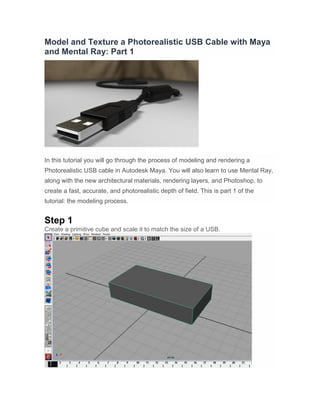
  • 1. Model and Texture a Photorealistic USB Cable with Maya and Mental Ray: Part 1 In this tutorial you will go through the process of modeling and rendering a Photorealistic USB cable in Autodesk Maya. You will also learn to use Mental Ray, along with the new architectural materials, rendering layers, and Photoshop, to create a fast, accurate, and photorealistic depth of field. This is part 1 of the tutorial: the modeling process. Step 1 Create a primitive cube and scale it to match the size of a USB.
  • 2. Step 2 Under the “Polygons” menu, go to the “Edit Mesh > Insert Edge Loop Tool". Step 3 Create 2 edge loops.
  • 3. Step 4 Select 8 vertexes from the end of the geometry, and with the scale and move tools, modify the geometry to match the basic shape of a USB. Step 5 This is how it should look (depending on the type of USB cable you are trying model).
  • 4. Step 6 Select the front face of the USB.
  • 5. Step 7 With that same face still selected, go to “Edit Mesh > Extrude”, and create an inner face.
  • 6. Step 8 Once again, go to “Edit Mesh > Extrude”, and extrude the face inward a bit.
  • 7. Step 9 Go to “Edit Mesh > Insert Edge Loop Tool", and add some edges, to create a new face on the top of the USB.
  • 8. Step 10 Select the new face, then go to “Edit Mesh > Extrude”, and extrude the face slightly inward.
  • 9. Step 11 Go to “Edit Mesh > Insert Edge Loop Tool”, and create 16 edges on the side of the USB.
  • 10. Step 12 Select 16 faces from the 32 you just created (every other one).
  • 11. Step 13 With those faces selected, go to “Edit Mesh > Extrude”, and extrude the faces inward as shown.
  • 12. Step 14 Scale the shape of the faces to make them smaller on the vertical axis.
  • 13. Step 15 This is how it should look on both sides.
  • 14. Step 16 Go to “Edit Mesh > Insert Edge Loop Tool”, and create 2 edges on the sides of the USB. If you get a problem like the one in the image, just go to the next step.
  • 15. Step 17 Go to “Edit Mesh > Split Polygon Tool”, click on the beginning of the line you want to create, and once again at the end. Do this for both edges, and for both sides of the USB.
  • 16. Step 18 Select all of the small faces that you just created on the sides of the USB, then go to “Edit Mesh > Extrude”, and extrude those faces inward.
  • 17. Step 19 You should have something that looks like this.
  • 18. Step 20 Go to “Edit Mesh > Split Polygon Tool”, and to “Edit Mesh > Insert Edge Loop Tool”. Using both tools as necessary, create edges at every hard angle change of the USB (use the images as reference).
  • 19.
  • 20. Step 21 When you are finished, select the USB object and simply press number 3 on your keyboard to smooth it. Then just sit back and watch how nice the smoothed USB looks.
  • 21. Step 22 Now, create a primitive cube, position it, and scale it to fit inside the USB.
  • 22. Step 23 Go to “Edit Mesh > Extrude”, and extrude the front face of the metal connector.
  • 23. Step 24 Once again, go to “Edit Mesh > Extrude”, and extrude the face inward.
  • 24. Step 25 Go to “Edit Mesh > Insert Edge Loop tool”, and create 2 edge loops through the middle of metal connector.
  • 25. Step 26 Select the small faces you just created, then go to “Edit Mesh > Extrude”, and extrude them slightly inward.
  • 26. Step 27 Go to “Edit Mesh > Insert Edge Loop tool”, and create some new edges to make 2 faces at the top of the connector.
  • 27. Step 28 Go to “Edit Mesh > Extrude”, and extrude the 2 faces inward.
  • 28. Step 29 Select the 2 faces and delete them to create 2 holes.
  • 29. Step 30 Now you are going to use a different method to smooth the object (this method can only be used with simple geometry). Go to “Edit Mesh > Bevel”, set the 'Width' to '0.6' (this will depend on how smooth you want the object to be, and also the size of the object). Also, set the 'Segments' to 1, the 'Offset type' to 'Fractional', the 'Offset space' to 'World', and the 'UV assignment' to 'Planar project per face'.
  • 30. Step 31 Now simply press number 3, and you should see some nice edges.
  • 31. Step 32 Make a primitive cube, and fit it inside the metal connector.
  • 32. Step 33 Go to “Edit Mesh > Bevel”, to smooth the cube.
  • 33. Step 34 Go to the “Create > EP Curve Tool”, and set the 'Curve degree' to '3 cubic' (this will create a nice curve).
  • 34. Step 35 Draw the cable as shown.
  • 35. Step 36 Select the control vertexes of the curve and adjust them to your liking.
  • 36. Step 37 This is how my curve looks, but you can make yours any way you like.
  • 37. Step 38 Make a primitive cylinder, and scale the diameter to match your cable.
  • 38. Step 39 Move the cylinder to the end of the curve.
  • 39. Step 40 Scale the cylinder to match the length of the cable.
  • 40. Step 41 Increase the 'Subdivisions Height' to at least 300.
  • 41. Step 42 Select the cylinder, press “shift”, and then select the curve (the order in which you select the objects is very important). Now, with the objects selected, go to “Animate > Motion Path > Attach to Motion Path" (in the “Animation” menu).
  • 42. Step 43 Move the time line to check if the object is moving properly.
  • 43. Step 44 Now we need to make the cylinder distort around the curve. So, with the cylinder selected, go to “Animate > Motion Paths > Flow Path Object”.
  • 44. Step 45 With the deformer you just created selected, change the 'T Divisions' to '400', and the cylinder should be following the curve smoothly.
  • 45. Step 46 To hide the deformers, go to “Show > Deformers” in the little menu on top of perspective view.
  • 46. Step 47 Now create a primitive plane for the floor.
  • 47. Step 48 To attach the cable to the USB, just create a primitive cylinder, and position it as shown.
  • 48. Step 49 In the “Polygons” menu, go to “Edit Mesh > Insert Edge Loop Tool”, and make some edges around the cylinder.
  • 49. Step 50 Select the faces that you want to extrude, then go to “Edit Mesh > Extrude”, and extrude them inward.
  • 50. Step 51 Create a primitive cylinder (this will be the thick portion of the cable).
  • 51. Step 52 Change the “Subdivisions Axis” to '50'.
  • 52. Step 53 Go to “Edit Mesh > Insert Edge Loop Tool”, and insert to 4 edges (2 on each side).
  • 53. Step 54 Select the vertexes at the end of the cylinder and scale them.
  • 54. Step 55 Do the same for the opposite side.
  • 55. Step 56 Go to “Edit Mesh > Insert Edge Loop tool”, and insert some edges at the hard angles of the cylinder.
  • 56. Step 57 Make sure it's the same for both sides.
  • 57. Step 58 Create small cylinders and position them were you want the holes to be.
  • 58. Step 59 Select the 4 cylinders, and go to “Mesh > Combine”.
  • 59. Step 60 Now you need to create some geometry for the holes (this is very important, because if you don´t do it, the hole could have some errors).
  • 60. Step 61 Select the big cylinder, press “shift”, and then select the small cylinders. Go to “Mesh > Booleans > Difference”.
  • 61. Step 62 This is how it should look (little holes without glitches). If you do get any problems, just move the edges around until they disappear.
  • 62. Step 63 Now position the cylinder where you want it to be.
  • 63. Step 64 Select the front faces from both sides.
  • 64. Step 65 Go to “Edit Mesh > Extrude”, and extrude the faces to make a smaller circle.
  • 65. Step 66 Select the new faces, go to “Edit Mesh > Extrude” and extrude them inward.
  • 66. Advertisement Step 67 This is how it should look (I have hidden the floor so you can see the results better).
  • 67. Step 68 For the background, I used a cloth included in a tutorial from the “Digital Tutors” series. You can check it out here: http://www.digitaltutors.com .