SlideShare ist ein Scribd-Unternehmen logo
1 von 22
Downloaden Sie, um offline zu lesen
ICT – TECHNICAL DRAFTING – Grade 10
175
Quarter IV Time Allotment: 24 hrs.
MODULE 7
DRAFTING MECHANICAL LAYOUT AND DETAILS
USING CAD
Introduction
The objective of an architectural design is to create an effective
environmental system. Structural thinking should be introduced at the early
stages in the design process. These will provide buildings and residential
dwellings with mechanical and other environmental subsystems to support
horizontal and vertical movement of men and materials. It also provides
functional heating, ventilating, air conditioning (HVAC) power, water and
waste disposal. In addition, acoustical and lighting needs are often influenced
by structural design.
The requirements for provisions of heating, ventilation, air conditioning,
power, water and waste services can be visualized in the form of a tree
diagram. These services usually originate at a centralized location and trace
their way horizontally and vertically throughout the structure to serve the
activity spaces.
The designer should be well versed with heating, ventilating, air
conditioning systems, as well as vertical transportation which include
escalators and elevators.
This module familiarizes you on how to locate the machines, raceways,
wirings, motors, generations and the like in its proper places.
Content Standard Performance Standard
The learner demonstrates
understanding of concepts and
underlying principles in drafting
mechanical layout and details using
CAD.
The learner independently drafts
mechanical layout and details using
CAD following the job requirements.
ICT – TECHNICAL DRAFTING – Grade 10
176
ENJOY YOUR JOURNEY!
Objectives:
Upon completion of this module, you are expected to draft:
 heating, ventilating, and air conditioning systems according to
Mechanical Code;
 mechanical details of conveyor system; and
 fire protection system using CAD.
*****
Pre – Assessment
You will be challenged to recall on your prior knowledge and previous
experiences about drafting mechanical layout details. This phase will guide
you in assessing yourself by answering questions that relate with the basics
of drafting mechanical lay-out and details.
Multiple Choice: Choose the letter of the correct answer. Write your answer
in the space provided to each number.
______1. It is a water supply pipe that extends vertically to one story or
more to carry water to fixtures.
A. riser B. soil pipe C. vent pipe D. waste pipe
______2. It is a vertical pipe that extends to one or more floors and carries
discharge of water closets and other similar fixtures.
ICT – TECHNICAL DRAFTING – Grade 10
177
A. sewer B. soil stack C. vent stack D. waste
stack
______3. It is a sewer used for carrying groundwater, rainwater, surface
water, or other non-polluting waste.
A. storm sewer B. vent stack C. sanitary sewer D. waste
stack
______4. A fitting with a removable plug that is placed in plumbing drainage
pipe lines to allow access for cleaning out the pipe.
A. cleanout B. drain C. stack D. trap
______5. A U-shaped pipe below plumbing fixtures that holds water to
prevent odor and sewer gas from entering the fixture.
A. drain B. fitting C. stack D. trap
______6. A pipe that carries the discharge of water closets or other similar
fixtures.
A. sewer B. soil pipe C. vent pipe D. waste pipe
______7. The portion of a pipe or fitting continuing in a straight line in the
direction of flow in which it is connected.
A. cleanout B. drain C. fitting D. run
______8. A vertical pipe that runs to one or more floors and carries the
discharge of fixtures other than water closets and similar fixtures.
A. sewer B. soil stack C. vent stack D. waste
stack
______9. A fitting that is used to control the flow of fluid or gas.
A. drain B. lavatory C. valve D. water
closet
_____10. The pipe installed to ventilate the building drainage system and to
prevent drawing liquid out of traps and stopping back pressure.
A. fitting B. riser C. soil pipe D. vent pipe
_____11. The inward flow of air through a porous wall or crack.
A. duct loss B. infiltration C. latent load D. R-factor
_____12. The indoor temperature less the outdoor temperature.
A. internal heat gain C. outdoor temperature
B. mechanical ventilation D. temperature difference
_____13. Amount of heat loss through mechanical ventilators such as range
hood fans or bathroom exhaust fans.
A. heat transfer multiplier C. outdoor temperature
B. mechanical ventilation D. temperature difference
_____14. Heat loss through ductwork in an unheated space, which has an
effect on total heat loss.
ICT – TECHNICAL DRAFTING – Grade 10
178
A. duct loss C. internal heat gain
B. indoor temperature D. outdoor temperature
_____15. A unit of measure determined by the amount of heat required to
raise 1 pound of water 1 degree Fahrenheit.
A. British Thermal Unit C. Degrees Fahrenheit
B. Degrees Centigrade D. Degrees Kelvin
Skills Assessment
Directions: Put a check (√) mark that corresponds to your level of
competency in performing the skills that relate with drafting mechanical layout
and details. Feel free to answer the assessment questionnaire on your
notebook.
Not much – means that you are not yet competent with the skills
stated.
A little – means you have skills but not adequate to perform the task.
A lot – means that you already possess the desired skills.
Skills in Drafting Mechanical Layout and
Details
A lot A
little
Not
much
I can draft heating, ventilating and air-conditioning
systems according to mechanical codes
I can indicate signs and symbols according to
mechanical layout and detail requirements
I know how to draw elevator, escalators,
dumbwaiter and moving ramp systems according
to mechanical codes
I can draw details of mechanical conveyor system
according to mechanical layout and detail
requirements
I know how to draw fire sprinkler system
according to fire code
I know how to draw signs and symbols of fire
ICT – TECHNICAL DRAFTING – Grade 10
179
protection system according to fire protection
requirement
Learning Goals and Targets
After reading the introduction and carefully answering the pre-
assessment skills test, you now have an idea of what you will be dealing in
this module. Now, prepare to set your goals and targets for this module by
completing the activity below. Write your answer in your notebook.
My goals are
My targets are
Goal 4
Goal 3
Goal 2
Goal 1
Target 1
Target 2
Target 3
ICT – TECHNICAL DRAFTING – Grade 10
180
Lesson 1: Drafting Heating, Ventilating and Air-Conditioning
(HVAC) Systems using CAD
In some HVAC AutoCAD software, you place the duct fittings and then the
software automatically sizes ducts in accordance with common mechanical
equipment manufacturer specifications. The floor plan is commonly used as a
background layer, and the HVAC plan is a separate layer. The following is a
sample of the steps that can be used by a draftsman to design and draw an
HVAC plan:
1. For the preliminary layout, draw the duct center lines, as shown in
below:
Know
ICT – TECHNICAL DRAFTING – Grade 10
181
Preliminary Layout of Duct Center Lines
2. Select supply and return registers from a symbol library, and add the
symbol to the end of the center lines where appropriate, as shown
below.
Automatic Placing Supply and Return Registers
3. Identify the lengths of individual duct runs, and tag each run. Locate
fittings by the type of intersection, as shown below.
ICT – TECHNICAL DRAFTING – Grade 10
182
Fittings located and identified
While all of this drawing information is added to the layout,
gather design information into a file for duct sizing based on specific
mechanical manufacturer specifications that you select.
Complete HVAC AutoCAD Layout
4. After the fitting location and sizes are determined, transform each
fitting into accurate double-line symbols.
ICT – TECHNICAL DRAFTING – Grade 10
183
HVAC AutoCAD Layout with Fitting Symbols
AutoCAD Mechanical Symbols Library
Figure 1. Common HVAC Symbols
Simple Heat Loss and Gain Calculations
Cooling capacity for a room is defined as the heat load in a room that
have to be removed in order to achieve a certain room temperature and
humidity. The typical design is set to 24°C temperature and 55% RH (Relative
ICT – TECHNICAL DRAFTING – Grade 10
184
Humidity).
Study shows that this combination of temperature and RH is the most
conducive for the human body. The unit used to measure heat load is BTU/hr
(British Thermal Unit). 1 BTU/hr is the heat energy needed to increase 1
pound of water by 1°F.
When choosing an air conditioner, usually a 1 HP (Horse Power)
equipment is able to remove 9,000 BTU/hr of heat. With better technology,
some machines are able to remove 10,000 BTU/hr of heat with the same
capacity. The higher the listed BTU/hr, the greater the cooling capacity.
Air Conditioning Calculations - Rule Of Thumb
Calculating the cooling capacity needed for your room is a complicated
process as there are many factors to consider. However, there is a simple
rule of thumb that you can use to estimate the required cooling capacity for
your room. Use this result to compare with the calculation done by the air
conditioning contractors for your own checking purposes.
Suggested Activity 1: Compute for a Required Window Air Conditioner
Capacity
Step 1: Find the volume of your room in cubic feet. This is done by measuring
the length, width and height of the room in feet and multiply all the three
dimensions together.
Volume = Width X Length X Height (cubic feet)
Step 2: Multiply this volume by 6.
C1 = Volume X 6
Step 3: Estimate the number of people (N) that will usually occupy this room.
Each person produces about 500 BTU/hr of heat for normal office-related
activity. Multiply this two figures together.
C2 = N x 500 BTU/hr
ICT – TECHNICAL DRAFTING – Grade 10
185
Step 4: Add C1 and C2 together and you will get a very simplified cooling
capacity needed for the room.
Estimated Cooling Capacity needed = C1 + C2 (BTU/hr)
Suggested Activity 2: HVAC Plan for a Simple Residential Building
Directions: Create an AutoCAD blocks for each of the HVAC Symbols and
save in a separate folder to be inserted in the Design Center. Then use the
floor plan from previous lessons to draft the HVAC Plan for a Simple
Residential Building as shown below.
Note: You may indicate the Simple Heat Loss and Gain Calculations from the
given drawing based on the dimensions. Make sure you have considered the outdoor
temperature and the number of occupant in the calculations.
ICT – TECHNICAL DRAFTING – Grade 10
186
HVAC Plan for a Simple Residential Building
Suggested Activity 3: Two- Storey HVAC Residential Plan
Directions: Create a Two-Storey HVAC Residential Floor Plan from previous
floor plans used in this module with Simple Heat Loss and Gain
Calculations
Know
ICT – TECHNICAL DRAFTING – Grade 10
187
Lesson 2:Drafting MechanicalDetails of Conveyor Systems
using CAD
Elevator Drawings
Elevators come in several models and sizes. In this activity, you will be
drafting a passenger elevator and a residential service elevator. Selecting the
model and size depends on several factors such as:
a. expected number of passengers
b. number of floors served
c. budget
d. speed
One of the main parts of the quoting and design processes is the
layout of conveyor systems. While most of the detailed conveyor systems is
done with Autodesk Inventor, (a 3D CAD software package), most of the
layout are still done in 2D in AutoCAD. It makes sense to use a 2D drafting
package as the files are much simpler and smaller in size allowing for easy
transfer.
Steps in Planning Mechanical Details of Conveyor Systems Design and
Standards
The following data is for typical industry size elevators. Any size cab is
available in Œ” increments to dimensions A and C or B and D within the
maximum and minimum dimensions shown in the diagram below not to
exceed 12 SQ. FT. or 15 SQ. FT.
The following specs are to be provided by the General Contractor
(GC), except as noted, prior to Elevator Contractor (EC) installing the elevator
equipment.
ICT – TECHNICAL DRAFTING – Grade 10
188
1. Environmental requirements for hoistway:
a. The temperature should be maintained between 400 F to 1250 F.
b. It should not be exposed to the elements.
2. Pit Requirements:
a. Substantial level pit floor slab to support 2,700 lbs. impact load.
b. Waterproof pit minimum 6” below lowest floor level.
Suggested Activity 1:
Directions: Based on the given information above, formulate at least ten
(10) planning guidelines to be considered in drafting Mechanical Details of
Conveyor Systems. Be sure to discuss your presentation in class
comprehensively.
Suggested Activity 2:
Directions: Draft the sample residential elevator/conveyor plan as shown
below.
ICT – TECHNICAL DRAFTING – Grade 10
189
Suggested Activity 3: Draft Residential Elevator/Conveyor Plan
Directions: Draft the sample residential elevator/conveyor plan as shown
below.
Lesson 3. Drafting Fire ProtectionSystemsusing CAD
Introduction
ICT – TECHNICAL DRAFTING – Grade 10
190
The protection of residential or building structures from the hazards of
fire is one utmost concern of everybody. It is important that there must be a
continued citizen’s awareness on the destruction brought by fire to life and
property. Planners, designers, and builders have their own contributions by
making their plans and construction conform to the Fire Code Requirements.
The scope of the lesson on Fire Protection System in building is limited
to the following factors and the preparation of plans is through computer-
aided drafting.
1. Water and water supply for fire fighting
2. Water pumping system
3. Standpipe and hoses
4. Sprinkler systems
Requirements for fire safety:
a. At least two means of exit in every residential room (such as a
doorway or window) should be present.
b. Exit doors must be at least 0.60 m wide.
c. Occupied rooms must be accessible.
d. All door locking devices must be easily disengaged from the inside
by quick release catches.
e. The path of travel from any room to an exit must not be through
another room subject to locking.
f. Passages from sleeping rooms to exits must be at least 0.90 wide.
g. Stairs must be at least 0.90 m wide.
h. Every sleeping room must have at least a window which can be
easily opened from the inside.
i. Storm windows, screens, burglar guards must have quick opening
devices.
j. Combustion heaters and stoves must not be located to block
escape in case of malfunction.
ICT – TECHNICAL DRAFTING – Grade 10
191
Suggested Activity 1: AutoCAD blocks for Fire Safety Symbols
Direction: Create an AutoCAD blocks for each of the Fire Safety Symbols
and save in a separate folder to be inserted in the Design Center.
Suggested Activity 2: Draft Fire Safety Protection Systems
ICT – TECHNICAL DRAFTING – Grade 10
192
Directions: Using the floor plan from previous lessons, draft the Fire Safety
Protection Systems according to Fire Safety Guidelines and requirements. Be
sure to present you work the class.
Suggested Activity 3
Directions: Research and compare with other Fire Safety Protection Plans
and come-up with the Best-Practices in creating Fire Safety Protection Plans
using AutoCAD. Be able to present your output in the class.
Post-Assessment
Answer the post assessment test below to determine
whether there is significant increase in your understanding of
Drafting Mechanical Layout and Details using CAD.
Multiple Choice: Choose the letter of the correct answer. Write your answer
in the space provided before each number.
______1. A water supply pipe that extends vertically to one story or more to
carry water to fixtures.
A. riser B. soil pipe C. vent pipe D. waste pipe
______2. A vertical pipe that extends to one or more floors and carries
discharge of water closets and other similar fixtures.
A. sewer B. soil stack C. vent stack D. waste
stack
______3. A sewer used for carrying groundwater, rainwater, surface water,
or other non-polluting waste.
A. storm sewer B. vent stack C. sanitary sewer D. waste stack
______4. A fitting with a removable plug that is placed in plumbing drainage
pipe lines to allow access for cleaning out the pipe.
ICT – TECHNICAL DRAFTING – Grade 10
193
A. cleanout B. drain C. stack D. trap
______5. A U-shaped pipe below plumbing fixtures that holds water to
prevent odor and sewer gas from entering the fixture.
A. drain B. fitting C. stack D. trap
______6. A pipe that carries the discharge of water closets or other similar
fixtures.
A. sewer B. soil pipe C. vent pipe D. waste pipe
______7. The portion of a pipe or fitting continuing in a straight line in the
direction of flow in which it is connected.
A. cleanout B. drain C. fitting D. run
______8. A vertical pipe that runs one or more floors and carries the
discharge of fixtures other than water closets and similar fixtures.
A. sewer B. soil stack C. vent stack D. waste stack
______9. A fitting that is used to control the flow of fluid or gas.
A. drain B. lavatory C. valve D. water closet
_____10. The pipe installed to ventilate the building drainage system and to
prevent drawing liquid out of traps and stopping back pressure.
A. fitting B. riser C. soil pipe D. vent pipe
_____11. The inward flow of air through a porous wall or crack.
A. duct loss B. infiltration C. latent load D. R-factor
_____12. The indoor temperature less the outdoor temperature.
A. internal heat gain C. outdoor temperature
B. mechanical ventilation D. temperature difference
_____13. Amount of heat loss through mechanical ventilators such as range
hood fans or bathroom exhaust fans.
A. heat transfer multiplier C. outdoor temperature
B. mechanical ventilation D. temperature difference
_____14. Heat loss through ductwork in an unheated space, which has an
effect on total heat loss.
A. duct loss C. internal heat gain
B. indoor temperature D. outdoor temperature
_____15. A unit of measure determined by the amount of heat required to
raise 1 pound of water 1 degree Fahrenheit.
A. British Thermal Unit C. Degrees Fahrenheit
B. Degrees Centigrade D. Degrees Kelvin
ICT – TECHNICAL DRAFTING – Grade 10
194
Appendix A.
Assessment Tool: Performance Rubrics
Name: ______________________________ Date: ______________
Year & Section: _______________
Criteria 5 points 3 points 1 point
Proficiency Perform the task
with competence
and exceptional
performance
Perform the task
with competence
and with standard
performance
Perform the task
with competence
but below
standard
performance
Method Followed the
given procedure
from start to
finish, observed
correct usage of
command tools
Followed the
given procedure,
noted once
incorrect usage
of command tools
Followed the
given procedure,
noted more than
once incorrect
usage of
command tools.
Accuracy Perform the task
with no error
Perform the task
with at least 1-2
errors
Perform the task
with more than 2
errors
Time
Management
Finish the work
on/before the
given time
Finish the work
after the given
time
Unable to finish
the work
Rating Scale:
Points Earned Numerical Rating Descriptive Rating
17 – 20 91 – 100 Outstanding
13 – 16 86 – 90 Very Good
9 – 12 81 – 85 Good
5 – 8 76 – 80 Fair
1 - 4 71 - 75 Needs Improvement
Teacher’s Comments:
ICT – TECHNICAL DRAFTING – Grade 10
195
Teacher’s Signature: _____________________ Date: _____________
Note: This assessment tool can also be used in the evaluation of the following
suggested activities:
A. Suggested Activity 2 (Reflect and Understand), page 153
B. Suggested Activity 3 (Transfer), page 154
C. Suggested Activity 2 (Reflect and Understand), page 156
D. Suggested Activity 3 (Transfer), page 157
E. Suggested Activity 1 (Process), page 158
F. Suggested Activity 3 (Transfer), page 159
Appendix B.
Product Scoring Rubrics
Name: _________________ Date: ________________
Year & Section: __________ Teacher: _____________
Criteria 5 points 3 points 1 point
Accuracy All computations
and/or solutions
were accurately
done
At least 1 to 2
computations
and/or solutions
were
inaccurately
done
More than 3
computations
and/or solutions
were
inaccurately
done
CAD Application
(Appropriateness
of
tools/commands
used)
Selection of CAD
tools/commands
was appropriate
At least one
CAD
tools/commands
was used
inappropriately
More two CAD
tools/commands
were used
inappropriately
Time Management Finished the task
10 minute before
the given time
Finished the task
on time
Unable to
finished the
given task
Rating Scale:
Points Earned Numerical Rating Descriptive Rating
12 – 15 91 – 100 Very Good
8 – 11 86 – 90 Good
4 – 7 81 – 85 Fair
1 - 3 75 – 80 Needs Improvement
ICT – TECHNICAL DRAFTING – Grade 10
196
Teacher’s Comments:
Teacher’s Signature: _____________________ Date: _____________
Note: This assessment tool can also be used in the evaluation of the following
suggested activities:
A. Suggested Activity 1 (Process), pages 155-156
B. Suggested Activity 2 (Reflect and Understand), page 159

Weitere Àhnliche Inhalte

Was ist angesagt?

DLL - Cookery 7&8 (1).doc
DLL - Cookery 7&8 (1).docDLL - Cookery 7&8 (1).doc
DLL - Cookery 7&8 (1).docRAMONVENEZUELA1
 
TLE - Mechanical Drafting (Learning Module)
TLE - Mechanical Drafting (Learning Module)TLE - Mechanical Drafting (Learning Module)
TLE - Mechanical Drafting (Learning Module)Markleen Guimbao
 
Masonry learning module
Masonry learning moduleMasonry learning module
Masonry learning moduleyongex123
 
EIM 7/8 Lesson 1: Prepare Electrical Tools and Materials
EIM 7/8 Lesson 1: Prepare Electrical Tools and MaterialsEIM 7/8 Lesson 1: Prepare Electrical Tools and Materials
EIM 7/8 Lesson 1: Prepare Electrical Tools and MaterialsBenandro Palor
 
T.L.E. GRADE 7 LESSONS
T.L.E. GRADE 7 LESSONST.L.E. GRADE 7 LESSONS
T.L.E. GRADE 7 LESSONSDayleen Hijosa
 
Carpentry Learning Module Grade 7 and Grade 8 Explanatory Course
Carpentry Learning Module Grade 7 and Grade 8 Explanatory CourseCarpentry Learning Module Grade 7 and Grade 8 Explanatory Course
Carpentry Learning Module Grade 7 and Grade 8 Explanatory CourseShaira Payumo
 
Carpentry 7. Interpreting Technical Drawings and Plans.pptx
Carpentry 7. Interpreting Technical Drawings and Plans.pptxCarpentry 7. Interpreting Technical Drawings and Plans.pptx
Carpentry 7. Interpreting Technical Drawings and Plans.pptxEDMARKPONCE2
 
TLE-7-8-Agriculture-and-Fishery-Arts-Crop-Production-ACP-I-II-and-Horticultur...
TLE-7-8-Agriculture-and-Fishery-Arts-Crop-Production-ACP-I-II-and-Horticultur...TLE-7-8-Agriculture-and-Fishery-Arts-Crop-Production-ACP-I-II-and-Horticultur...
TLE-7-8-Agriculture-and-Fishery-Arts-Crop-Production-ACP-I-II-and-Horticultur...EvangelineLisa1
 
K to 12 TLE Curriculum Guide for Commercial Cooking
K to 12 TLE Curriculum Guide for Commercial CookingK to 12 TLE Curriculum Guide for Commercial Cooking
K to 12 TLE Curriculum Guide for Commercial CookingDr. Joy Kenneth Sala Biasong
 
Module 5 module 3 draft electrical and electronic layout and details
Module 5   module 3 draft electrical and electronic layout and detailsModule 5   module 3 draft electrical and electronic layout and details
Module 5 module 3 draft electrical and electronic layout and detailsGilbert Bautista
 
TLE 8 - TECHNICAL DRAFTING (PERFORM BASIC MENSURATION AND CALCULATION)
TLE 8 - TECHNICAL DRAFTING (PERFORM BASIC MENSURATION AND CALCULATION) TLE 8 - TECHNICAL DRAFTING (PERFORM BASIC MENSURATION AND CALCULATION)
TLE 8 - TECHNICAL DRAFTING (PERFORM BASIC MENSURATION AND CALCULATION) MichaellaApale
 
ICT: Computer Hardware Services - Lesson 1 use hand tools by Je-Jireh Silva
ICT: Computer Hardware Services - Lesson 1 use hand tools by Je-Jireh SilvaICT: Computer Hardware Services - Lesson 1 use hand tools by Je-Jireh Silva
ICT: Computer Hardware Services - Lesson 1 use hand tools by Je-Jireh SilvaJe-Jireh Silva
 
Staking out building lines
Staking out building linesStaking out building lines
Staking out building linesDioni Kiat
 
TLE 7-8 ICT-CSS Q1_M3 for printing.pdf
TLE 7-8 ICT-CSS Q1_M3 for printing.pdfTLE 7-8 ICT-CSS Q1_M3 for printing.pdf
TLE 7-8 ICT-CSS Q1_M3 for printing.pdfXyrevManeclang
 
Lesson plan in tools and equippment grade 10 cookery
Lesson plan in tools and equippment grade 10 cookeryLesson plan in tools and equippment grade 10 cookery
Lesson plan in tools and equippment grade 10 cookerycarlo mabubay
 

Was ist angesagt? (20)

K to 12 Electrical Learning Module
K to 12 Electrical Learning ModuleK to 12 Electrical Learning Module
K to 12 Electrical Learning Module
 
DLL - Cookery 7&8 (1).doc
DLL - Cookery 7&8 (1).docDLL - Cookery 7&8 (1).doc
DLL - Cookery 7&8 (1).doc
 
TLE/HE Handicraft Curriculum Guide
TLE/HE  Handicraft Curriculum GuideTLE/HE  Handicraft Curriculum Guide
TLE/HE Handicraft Curriculum Guide
 
TLE - Mechanical Drafting (Learning Module)
TLE - Mechanical Drafting (Learning Module)TLE - Mechanical Drafting (Learning Module)
TLE - Mechanical Drafting (Learning Module)
 
K to 12 dressmaking and tailoring learning modules
K to 12 dressmaking and tailoring learning modulesK to 12 dressmaking and tailoring learning modules
K to 12 dressmaking and tailoring learning modules
 
TLE/HE Household Services Curriculum Guide
TLE/HE  Household Services Curriculum Guide  TLE/HE  Household Services Curriculum Guide
TLE/HE Household Services Curriculum Guide
 
Masonry learning module
Masonry learning moduleMasonry learning module
Masonry learning module
 
EIM 7/8 Lesson 1: Prepare Electrical Tools and Materials
EIM 7/8 Lesson 1: Prepare Electrical Tools and MaterialsEIM 7/8 Lesson 1: Prepare Electrical Tools and Materials
EIM 7/8 Lesson 1: Prepare Electrical Tools and Materials
 
T.L.E. GRADE 7 LESSONS
T.L.E. GRADE 7 LESSONST.L.E. GRADE 7 LESSONS
T.L.E. GRADE 7 LESSONS
 
Carpentry Learning Module Grade 7 and Grade 8 Explanatory Course
Carpentry Learning Module Grade 7 and Grade 8 Explanatory CourseCarpentry Learning Module Grade 7 and Grade 8 Explanatory Course
Carpentry Learning Module Grade 7 and Grade 8 Explanatory Course
 
Carpentry 7. Interpreting Technical Drawings and Plans.pptx
Carpentry 7. Interpreting Technical Drawings and Plans.pptxCarpentry 7. Interpreting Technical Drawings and Plans.pptx
Carpentry 7. Interpreting Technical Drawings and Plans.pptx
 
TLE-7-8-Agriculture-and-Fishery-Arts-Crop-Production-ACP-I-II-and-Horticultur...
TLE-7-8-Agriculture-and-Fishery-Arts-Crop-Production-ACP-I-II-and-Horticultur...TLE-7-8-Agriculture-and-Fishery-Arts-Crop-Production-ACP-I-II-and-Horticultur...
TLE-7-8-Agriculture-and-Fishery-Arts-Crop-Production-ACP-I-II-and-Horticultur...
 
K to 12 TLE Curriculum Guide for Commercial Cooking
K to 12 TLE Curriculum Guide for Commercial CookingK to 12 TLE Curriculum Guide for Commercial Cooking
K to 12 TLE Curriculum Guide for Commercial Cooking
 
Module 5 module 3 draft electrical and electronic layout and details
Module 5   module 3 draft electrical and electronic layout and detailsModule 5   module 3 draft electrical and electronic layout and details
Module 5 module 3 draft electrical and electronic layout and details
 
TLE 8 - TECHNICAL DRAFTING (PERFORM BASIC MENSURATION AND CALCULATION)
TLE 8 - TECHNICAL DRAFTING (PERFORM BASIC MENSURATION AND CALCULATION) TLE 8 - TECHNICAL DRAFTING (PERFORM BASIC MENSURATION AND CALCULATION)
TLE 8 - TECHNICAL DRAFTING (PERFORM BASIC MENSURATION AND CALCULATION)
 
TLE/ HE Beauty Care Curriculum Guide
TLE/ HE Beauty Care Curriculum GuideTLE/ HE Beauty Care Curriculum Guide
TLE/ HE Beauty Care Curriculum Guide
 
ICT: Computer Hardware Services - Lesson 1 use hand tools by Je-Jireh Silva
ICT: Computer Hardware Services - Lesson 1 use hand tools by Je-Jireh SilvaICT: Computer Hardware Services - Lesson 1 use hand tools by Je-Jireh Silva
ICT: Computer Hardware Services - Lesson 1 use hand tools by Je-Jireh Silva
 
Staking out building lines
Staking out building linesStaking out building lines
Staking out building lines
 
TLE 7-8 ICT-CSS Q1_M3 for printing.pdf
TLE 7-8 ICT-CSS Q1_M3 for printing.pdfTLE 7-8 ICT-CSS Q1_M3 for printing.pdf
TLE 7-8 ICT-CSS Q1_M3 for printing.pdf
 
Lesson plan in tools and equippment grade 10 cookery
Lesson plan in tools and equippment grade 10 cookeryLesson plan in tools and equippment grade 10 cookery
Lesson plan in tools and equippment grade 10 cookery
 

Andere mochten auch

Module 7 module 5 draft mechanical layout and details
Module 7   module 5 draft mechanical layout and detailsModule 7   module 5 draft mechanical layout and details
Module 7 module 5 draft mechanical layout and detailsGilbert Bautista
 
Module 4 module 2 structural layout & details
Module 4   module 2 structural layout & detailsModule 4   module 2 structural layout & details
Module 4 module 2 structural layout & detailsGilbert Bautista
 
Module 3 module 1 architecural layout & details
Module 3   module 1 architecural layout & detailsModule 3   module 1 architecural layout & details
Module 3 module 1 architecural layout & detailsGilbert Bautista
 
TLE_ICT Teachnical Drafting Grade 10
TLE_ICT Teachnical Drafting Grade 10TLE_ICT Teachnical Drafting Grade 10
TLE_ICT Teachnical Drafting Grade 10Markleen Guimbao
 
K-12 Technical Drafting Learning Module
K-12 Technical Drafting Learning ModuleK-12 Technical Drafting Learning Module
K-12 Technical Drafting Learning ModuleMarkleen Guimbao
 
Technical Drafting Learning Module v.2.0
Technical Drafting Learning Module v.2.0Technical Drafting Learning Module v.2.0
Technical Drafting Learning Module v.2.0Bogs De Castro
 
Module 6 module 4 draft sanitary and plumbing layout and details
Module 6   module 4 draft sanitary and plumbing layout and details Module 6   module 4 draft sanitary and plumbing layout and details
Module 6 module 4 draft sanitary and plumbing layout and details Gilbert Bautista
 

Andere mochten auch (7)

Module 7 module 5 draft mechanical layout and details
Module 7   module 5 draft mechanical layout and detailsModule 7   module 5 draft mechanical layout and details
Module 7 module 5 draft mechanical layout and details
 
Module 4 module 2 structural layout & details
Module 4   module 2 structural layout & detailsModule 4   module 2 structural layout & details
Module 4 module 2 structural layout & details
 
Module 3 module 1 architecural layout & details
Module 3   module 1 architecural layout & detailsModule 3   module 1 architecural layout & details
Module 3 module 1 architecural layout & details
 
TLE_ICT Teachnical Drafting Grade 10
TLE_ICT Teachnical Drafting Grade 10TLE_ICT Teachnical Drafting Grade 10
TLE_ICT Teachnical Drafting Grade 10
 
K-12 Technical Drafting Learning Module
K-12 Technical Drafting Learning ModuleK-12 Technical Drafting Learning Module
K-12 Technical Drafting Learning Module
 
Technical Drafting Learning Module v.2.0
Technical Drafting Learning Module v.2.0Technical Drafting Learning Module v.2.0
Technical Drafting Learning Module v.2.0
 
Module 6 module 4 draft sanitary and plumbing layout and details
Module 6   module 4 draft sanitary and plumbing layout and details Module 6   module 4 draft sanitary and plumbing layout and details
Module 6 module 4 draft sanitary and plumbing layout and details
 

Ähnlich wie Technical Drafting Module 7

Module7 module5draftmechanicallayoutanddetails-140806060337-phpapp02
Module7 module5draftmechanicallayoutanddetails-140806060337-phpapp02Module7 module5draftmechanicallayoutanddetails-140806060337-phpapp02
Module7 module5draftmechanicallayoutanddetails-140806060337-phpapp02JicelleBayan
 
Module 7 module 5 draft mechanical layout and details
Module 7   module 5 draft mechanical layout and detailsModule 7   module 5 draft mechanical layout and details
Module 7 module 5 draft mechanical layout and detailsGilbert Bautista
 
Technical Drafting Module 6
Technical Drafting Module 6Technical Drafting Module 6
Technical Drafting Module 6DepEd
 
Design of an Air Distribution System for a Multi Storey Office Building
Design of an Air Distribution System for a Multi Storey Office BuildingDesign of an Air Distribution System for a Multi Storey Office Building
Design of an Air Distribution System for a Multi Storey Office Buildingijtsrd
 
Technical Drafting Module 5
Technical Drafting Module 5Technical Drafting Module 5
Technical Drafting Module 5DepEd
 
SYED (HVAC ENGINEER)
SYED (HVAC ENGINEER)SYED (HVAC ENGINEER)
SYED (HVAC ENGINEER)syed ali
 
Amol Dhobale resume(1)
Amol Dhobale resume(1)Amol Dhobale resume(1)
Amol Dhobale resume(1)DHOBALEA
 
The Role of CFD in Real Life Designs
The Role of CFD in Real Life DesignsThe Role of CFD in Real Life Designs
The Role of CFD in Real Life DesignsSOLIDWORKS
 
HVAC Design Course Content For Regular & Weekend Batch
HVAC Design Course Content For Regular & Weekend BatchHVAC Design Course Content For Regular & Weekend Batch
HVAC Design Course Content For Regular & Weekend BatchMECCI Engineers Private Limited
 
Afcom air control solution presentation
Afcom air control solution presentation Afcom air control solution presentation
Afcom air control solution presentation stacygriggs
 
Comparison between Systems
Comparison between SystemsComparison between Systems
Comparison between SystemsVictor Ashkenazy
 
CV_Ashu Bhatt
CV_Ashu BhattCV_Ashu Bhatt
CV_Ashu BhattAshu Bhatt
 
2015 x472 class 02 - generation systems
2015 x472 class 02 - generation systems2015 x472 class 02 - generation systems
2015 x472 class 02 - generation systemsmichaeljmack
 
IRJET- AC Room Design on HVAC
IRJET- AC Room Design on HVACIRJET- AC Room Design on HVAC
IRJET- AC Room Design on HVACIRJET Journal
 

Ähnlich wie Technical Drafting Module 7 (20)

Module7 module5draftmechanicallayoutanddetails-140806060337-phpapp02
Module7 module5draftmechanicallayoutanddetails-140806060337-phpapp02Module7 module5draftmechanicallayoutanddetails-140806060337-phpapp02
Module7 module5draftmechanicallayoutanddetails-140806060337-phpapp02
 
Module 7 module 5 draft mechanical layout and details
Module 7   module 5 draft mechanical layout and detailsModule 7   module 5 draft mechanical layout and details
Module 7 module 5 draft mechanical layout and details
 
RAJESH_RESUME
RAJESH_RESUMERAJESH_RESUME
RAJESH_RESUME
 
Technical Drafting Module 6
Technical Drafting Module 6Technical Drafting Module 6
Technical Drafting Module 6
 
Your permit office and ACCA Manual J, S and D
Your permit office and ACCA Manual J, S and DYour permit office and ACCA Manual J, S and D
Your permit office and ACCA Manual J, S and D
 
Resume
ResumeResume
Resume
 
Design of an Air Distribution System for a Multi Storey Office Building
Design of an Air Distribution System for a Multi Storey Office BuildingDesign of an Air Distribution System for a Multi Storey Office Building
Design of an Air Distribution System for a Multi Storey Office Building
 
Design HVAC System for Hospital
Design HVAC System for Hospital Design HVAC System for Hospital
Design HVAC System for Hospital
 
Technical Drafting Module 5
Technical Drafting Module 5Technical Drafting Module 5
Technical Drafting Module 5
 
Final presentation
Final presentationFinal presentation
Final presentation
 
SYED (HVAC ENGINEER)
SYED (HVAC ENGINEER)SYED (HVAC ENGINEER)
SYED (HVAC ENGINEER)
 
Amol Dhobale resume(1)
Amol Dhobale resume(1)Amol Dhobale resume(1)
Amol Dhobale resume(1)
 
The Role of CFD in Real Life Designs
The Role of CFD in Real Life DesignsThe Role of CFD in Real Life Designs
The Role of CFD in Real Life Designs
 
HVAC Design Course Content For Regular & Weekend Batch
HVAC Design Course Content For Regular & Weekend BatchHVAC Design Course Content For Regular & Weekend Batch
HVAC Design Course Content For Regular & Weekend Batch
 
Afcom air control solution presentation
Afcom air control solution presentation Afcom air control solution presentation
Afcom air control solution presentation
 
Eliminating Data Center Hot Spots
Eliminating Data Center Hot SpotsEliminating Data Center Hot Spots
Eliminating Data Center Hot Spots
 
Comparison between Systems
Comparison between SystemsComparison between Systems
Comparison between Systems
 
CV_Ashu Bhatt
CV_Ashu BhattCV_Ashu Bhatt
CV_Ashu Bhatt
 
2015 x472 class 02 - generation systems
2015 x472 class 02 - generation systems2015 x472 class 02 - generation systems
2015 x472 class 02 - generation systems
 
IRJET- AC Room Design on HVAC
IRJET- AC Room Design on HVACIRJET- AC Room Design on HVAC
IRJET- AC Room Design on HVAC
 

KĂŒrzlich hochgeladen

Past, Present and Future of Generative AI
Past, Present and Future of Generative AIPast, Present and Future of Generative AI
Past, Present and Future of Generative AIabhishek36461
 
Correctly Loading Incremental Data at Scale
Correctly Loading Incremental Data at ScaleCorrectly Loading Incremental Data at Scale
Correctly Loading Incremental Data at ScaleAlluxio, Inc.
 
Concrete Mix Design - IS 10262-2019 - .pptx
Concrete Mix Design - IS 10262-2019 - .pptxConcrete Mix Design - IS 10262-2019 - .pptx
Concrete Mix Design - IS 10262-2019 - .pptxKartikeyaDwivedi3
 
Indian Dairy Industry Present Status and.ppt
Indian Dairy Industry Present Status and.pptIndian Dairy Industry Present Status and.ppt
Indian Dairy Industry Present Status and.pptMadan Karki
 
computer application and construction management
computer application and construction managementcomputer application and construction management
computer application and construction managementMariconPadriquez1
 
CCS355 Neural Network & Deep Learning Unit II Notes with Question bank .pdf
CCS355 Neural Network & Deep Learning Unit II Notes with Question bank .pdfCCS355 Neural Network & Deep Learning Unit II Notes with Question bank .pdf
CCS355 Neural Network & Deep Learning Unit II Notes with Question bank .pdfAsst.prof M.Gokilavani
 
IVE Industry Focused Event - Defence Sector 2024
IVE Industry Focused Event - Defence Sector 2024IVE Industry Focused Event - Defence Sector 2024
IVE Industry Focused Event - Defence Sector 2024Mark Billinghurst
 
Architect Hassan Khalil Portfolio for 2024
Architect Hassan Khalil Portfolio for 2024Architect Hassan Khalil Portfolio for 2024
Architect Hassan Khalil Portfolio for 2024hassan khalil
 
Arduino_CSE ece ppt for working and principal of arduino.ppt
Arduino_CSE ece ppt for working and principal of arduino.pptArduino_CSE ece ppt for working and principal of arduino.ppt
Arduino_CSE ece ppt for working and principal of arduino.pptSAURABHKUMAR892774
 
Introduction to Machine Learning Unit-3 for II MECH
Introduction to Machine Learning Unit-3 for II MECHIntroduction to Machine Learning Unit-3 for II MECH
Introduction to Machine Learning Unit-3 for II MECHC Sai Kiran
 
Software and Systems Engineering Standards: Verification and Validation of Sy...
Software and Systems Engineering Standards: Verification and Validation of Sy...Software and Systems Engineering Standards: Verification and Validation of Sy...
Software and Systems Engineering Standards: Verification and Validation of Sy...VICTOR MAESTRE RAMIREZ
 
Why does (not) Kafka need fsync: Eliminating tail latency spikes caused by fsync
Why does (not) Kafka need fsync: Eliminating tail latency spikes caused by fsyncWhy does (not) Kafka need fsync: Eliminating tail latency spikes caused by fsync
Why does (not) Kafka need fsync: Eliminating tail latency spikes caused by fsyncssuser2ae721
 
Oxy acetylene welding presentation note.
Oxy acetylene welding presentation note.Oxy acetylene welding presentation note.
Oxy acetylene welding presentation note.eptoze12
 
lifi-technology with integration of IOT.pptx
lifi-technology with integration of IOT.pptxlifi-technology with integration of IOT.pptx
lifi-technology with integration of IOT.pptxsomshekarkn64
 
welding defects observed during the welding
welding defects observed during the weldingwelding defects observed during the welding
welding defects observed during the weldingMuhammadUzairLiaqat
 
🔝9953056974🔝!!-YOUNG call girls in Rajendra Nagar Escort rvice Shot 2000 nigh...
🔝9953056974🔝!!-YOUNG call girls in Rajendra Nagar Escort rvice Shot 2000 nigh...🔝9953056974🔝!!-YOUNG call girls in Rajendra Nagar Escort rvice Shot 2000 nigh...
🔝9953056974🔝!!-YOUNG call girls in Rajendra Nagar Escort rvice Shot 2000 nigh...9953056974 Low Rate Call Girls In Saket, Delhi NCR
 
Application of Residue Theorem to evaluate real integrations.pptx
Application of Residue Theorem to evaluate real integrations.pptxApplication of Residue Theorem to evaluate real integrations.pptx
Application of Residue Theorem to evaluate real integrations.pptx959SahilShah
 
Instrumentation, measurement and control of bio process parameters ( Temperat...
Instrumentation, measurement and control of bio process parameters ( Temperat...Instrumentation, measurement and control of bio process parameters ( Temperat...
Instrumentation, measurement and control of bio process parameters ( Temperat...121011101441
 

KĂŒrzlich hochgeladen (20)

Past, Present and Future of Generative AI
Past, Present and Future of Generative AIPast, Present and Future of Generative AI
Past, Present and Future of Generative AI
 
Correctly Loading Incremental Data at Scale
Correctly Loading Incremental Data at ScaleCorrectly Loading Incremental Data at Scale
Correctly Loading Incremental Data at Scale
 
9953056974 Call Girls In South Ex, Escorts (Delhi) NCR.pdf
9953056974 Call Girls In South Ex, Escorts (Delhi) NCR.pdf9953056974 Call Girls In South Ex, Escorts (Delhi) NCR.pdf
9953056974 Call Girls In South Ex, Escorts (Delhi) NCR.pdf
 
Concrete Mix Design - IS 10262-2019 - .pptx
Concrete Mix Design - IS 10262-2019 - .pptxConcrete Mix Design - IS 10262-2019 - .pptx
Concrete Mix Design - IS 10262-2019 - .pptx
 
Indian Dairy Industry Present Status and.ppt
Indian Dairy Industry Present Status and.pptIndian Dairy Industry Present Status and.ppt
Indian Dairy Industry Present Status and.ppt
 
computer application and construction management
computer application and construction managementcomputer application and construction management
computer application and construction management
 
CCS355 Neural Network & Deep Learning Unit II Notes with Question bank .pdf
CCS355 Neural Network & Deep Learning Unit II Notes with Question bank .pdfCCS355 Neural Network & Deep Learning Unit II Notes with Question bank .pdf
CCS355 Neural Network & Deep Learning Unit II Notes with Question bank .pdf
 
IVE Industry Focused Event - Defence Sector 2024
IVE Industry Focused Event - Defence Sector 2024IVE Industry Focused Event - Defence Sector 2024
IVE Industry Focused Event - Defence Sector 2024
 
Architect Hassan Khalil Portfolio for 2024
Architect Hassan Khalil Portfolio for 2024Architect Hassan Khalil Portfolio for 2024
Architect Hassan Khalil Portfolio for 2024
 
Arduino_CSE ece ppt for working and principal of arduino.ppt
Arduino_CSE ece ppt for working and principal of arduino.pptArduino_CSE ece ppt for working and principal of arduino.ppt
Arduino_CSE ece ppt for working and principal of arduino.ppt
 
Design and analysis of solar grass cutter.pdf
Design and analysis of solar grass cutter.pdfDesign and analysis of solar grass cutter.pdf
Design and analysis of solar grass cutter.pdf
 
Introduction to Machine Learning Unit-3 for II MECH
Introduction to Machine Learning Unit-3 for II MECHIntroduction to Machine Learning Unit-3 for II MECH
Introduction to Machine Learning Unit-3 for II MECH
 
Software and Systems Engineering Standards: Verification and Validation of Sy...
Software and Systems Engineering Standards: Verification and Validation of Sy...Software and Systems Engineering Standards: Verification and Validation of Sy...
Software and Systems Engineering Standards: Verification and Validation of Sy...
 
Why does (not) Kafka need fsync: Eliminating tail latency spikes caused by fsync
Why does (not) Kafka need fsync: Eliminating tail latency spikes caused by fsyncWhy does (not) Kafka need fsync: Eliminating tail latency spikes caused by fsync
Why does (not) Kafka need fsync: Eliminating tail latency spikes caused by fsync
 
Oxy acetylene welding presentation note.
Oxy acetylene welding presentation note.Oxy acetylene welding presentation note.
Oxy acetylene welding presentation note.
 
lifi-technology with integration of IOT.pptx
lifi-technology with integration of IOT.pptxlifi-technology with integration of IOT.pptx
lifi-technology with integration of IOT.pptx
 
welding defects observed during the welding
welding defects observed during the weldingwelding defects observed during the welding
welding defects observed during the welding
 
🔝9953056974🔝!!-YOUNG call girls in Rajendra Nagar Escort rvice Shot 2000 nigh...
🔝9953056974🔝!!-YOUNG call girls in Rajendra Nagar Escort rvice Shot 2000 nigh...🔝9953056974🔝!!-YOUNG call girls in Rajendra Nagar Escort rvice Shot 2000 nigh...
🔝9953056974🔝!!-YOUNG call girls in Rajendra Nagar Escort rvice Shot 2000 nigh...
 
Application of Residue Theorem to evaluate real integrations.pptx
Application of Residue Theorem to evaluate real integrations.pptxApplication of Residue Theorem to evaluate real integrations.pptx
Application of Residue Theorem to evaluate real integrations.pptx
 
Instrumentation, measurement and control of bio process parameters ( Temperat...
Instrumentation, measurement and control of bio process parameters ( Temperat...Instrumentation, measurement and control of bio process parameters ( Temperat...
Instrumentation, measurement and control of bio process parameters ( Temperat...
 

Technical Drafting Module 7

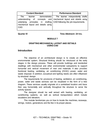
  • 1. ICT – TECHNICAL DRAFTING – Grade 10 175 Quarter IV Time Allotment: 24 hrs. MODULE 7 DRAFTING MECHANICAL LAYOUT AND DETAILS USING CAD Introduction The objective of an architectural design is to create an effective environmental system. Structural thinking should be introduced at the early stages in the design process. These will provide buildings and residential dwellings with mechanical and other environmental subsystems to support horizontal and vertical movement of men and materials. It also provides functional heating, ventilating, air conditioning (HVAC) power, water and waste disposal. In addition, acoustical and lighting needs are often influenced by structural design. The requirements for provisions of heating, ventilation, air conditioning, power, water and waste services can be visualized in the form of a tree diagram. These services usually originate at a centralized location and trace their way horizontally and vertically throughout the structure to serve the activity spaces. The designer should be well versed with heating, ventilating, air conditioning systems, as well as vertical transportation which include escalators and elevators. This module familiarizes you on how to locate the machines, raceways, wirings, motors, generations and the like in its proper places. Content Standard Performance Standard The learner demonstrates understanding of concepts and underlying principles in drafting mechanical layout and details using CAD. The learner independently drafts mechanical layout and details using CAD following the job requirements.
  • 2. ICT – TECHNICAL DRAFTING – Grade 10 176 ENJOY YOUR JOURNEY! Objectives: Upon completion of this module, you are expected to draft:  heating, ventilating, and air conditioning systems according to Mechanical Code;  mechanical details of conveyor system; and  fire protection system using CAD. ***** Pre – Assessment You will be challenged to recall on your prior knowledge and previous experiences about drafting mechanical layout details. This phase will guide you in assessing yourself by answering questions that relate with the basics of drafting mechanical lay-out and details. Multiple Choice: Choose the letter of the correct answer. Write your answer in the space provided to each number. ______1. It is a water supply pipe that extends vertically to one story or more to carry water to fixtures. A. riser B. soil pipe C. vent pipe D. waste pipe ______2. It is a vertical pipe that extends to one or more floors and carries discharge of water closets and other similar fixtures.
  • 3. ICT – TECHNICAL DRAFTING – Grade 10 177 A. sewer B. soil stack C. vent stack D. waste stack ______3. It is a sewer used for carrying groundwater, rainwater, surface water, or other non-polluting waste. A. storm sewer B. vent stack C. sanitary sewer D. waste stack ______4. A fitting with a removable plug that is placed in plumbing drainage pipe lines to allow access for cleaning out the pipe. A. cleanout B. drain C. stack D. trap ______5. A U-shaped pipe below plumbing fixtures that holds water to prevent odor and sewer gas from entering the fixture. A. drain B. fitting C. stack D. trap ______6. A pipe that carries the discharge of water closets or other similar fixtures. A. sewer B. soil pipe C. vent pipe D. waste pipe ______7. The portion of a pipe or fitting continuing in a straight line in the direction of flow in which it is connected. A. cleanout B. drain C. fitting D. run ______8. A vertical pipe that runs to one or more floors and carries the discharge of fixtures other than water closets and similar fixtures. A. sewer B. soil stack C. vent stack D. waste stack ______9. A fitting that is used to control the flow of fluid or gas. A. drain B. lavatory C. valve D. water closet _____10. The pipe installed to ventilate the building drainage system and to prevent drawing liquid out of traps and stopping back pressure. A. fitting B. riser C. soil pipe D. vent pipe _____11. The inward flow of air through a porous wall or crack. A. duct loss B. infiltration C. latent load D. R-factor _____12. The indoor temperature less the outdoor temperature. A. internal heat gain C. outdoor temperature B. mechanical ventilation D. temperature difference _____13. Amount of heat loss through mechanical ventilators such as range hood fans or bathroom exhaust fans. A. heat transfer multiplier C. outdoor temperature B. mechanical ventilation D. temperature difference _____14. Heat loss through ductwork in an unheated space, which has an effect on total heat loss.
  • 4. ICT – TECHNICAL DRAFTING – Grade 10 178 A. duct loss C. internal heat gain B. indoor temperature D. outdoor temperature _____15. A unit of measure determined by the amount of heat required to raise 1 pound of water 1 degree Fahrenheit. A. British Thermal Unit C. Degrees Fahrenheit B. Degrees Centigrade D. Degrees Kelvin Skills Assessment Directions: Put a check (√) mark that corresponds to your level of competency in performing the skills that relate with drafting mechanical layout and details. Feel free to answer the assessment questionnaire on your notebook. Not much – means that you are not yet competent with the skills stated. A little – means you have skills but not adequate to perform the task. A lot – means that you already possess the desired skills. Skills in Drafting Mechanical Layout and Details A lot A little Not much I can draft heating, ventilating and air-conditioning systems according to mechanical codes I can indicate signs and symbols according to mechanical layout and detail requirements I know how to draw elevator, escalators, dumbwaiter and moving ramp systems according to mechanical codes I can draw details of mechanical conveyor system according to mechanical layout and detail requirements I know how to draw fire sprinkler system according to fire code I know how to draw signs and symbols of fire
  • 5. ICT – TECHNICAL DRAFTING – Grade 10 179 protection system according to fire protection requirement Learning Goals and Targets After reading the introduction and carefully answering the pre- assessment skills test, you now have an idea of what you will be dealing in this module. Now, prepare to set your goals and targets for this module by completing the activity below. Write your answer in your notebook. My goals are My targets are Goal 4 Goal 3 Goal 2 Goal 1 Target 1 Target 2 Target 3
  • 6. ICT – TECHNICAL DRAFTING – Grade 10 180 Lesson 1: Drafting Heating, Ventilating and Air-Conditioning (HVAC) Systems using CAD In some HVAC AutoCAD software, you place the duct fittings and then the software automatically sizes ducts in accordance with common mechanical equipment manufacturer specifications. The floor plan is commonly used as a background layer, and the HVAC plan is a separate layer. The following is a sample of the steps that can be used by a draftsman to design and draw an HVAC plan: 1. For the preliminary layout, draw the duct center lines, as shown in below: Know
  • 7. ICT – TECHNICAL DRAFTING – Grade 10 181 Preliminary Layout of Duct Center Lines 2. Select supply and return registers from a symbol library, and add the symbol to the end of the center lines where appropriate, as shown below. Automatic Placing Supply and Return Registers 3. Identify the lengths of individual duct runs, and tag each run. Locate fittings by the type of intersection, as shown below.
  • 8. ICT – TECHNICAL DRAFTING – Grade 10 182 Fittings located and identified While all of this drawing information is added to the layout, gather design information into a file for duct sizing based on specific mechanical manufacturer specifications that you select. Complete HVAC AutoCAD Layout 4. After the fitting location and sizes are determined, transform each fitting into accurate double-line symbols.
  • 9. ICT – TECHNICAL DRAFTING – Grade 10 183 HVAC AutoCAD Layout with Fitting Symbols AutoCAD Mechanical Symbols Library Figure 1. Common HVAC Symbols Simple Heat Loss and Gain Calculations Cooling capacity for a room is defined as the heat load in a room that have to be removed in order to achieve a certain room temperature and humidity. The typical design is set to 24°C temperature and 55% RH (Relative
  • 10. ICT – TECHNICAL DRAFTING – Grade 10 184 Humidity). Study shows that this combination of temperature and RH is the most conducive for the human body. The unit used to measure heat load is BTU/hr (British Thermal Unit). 1 BTU/hr is the heat energy needed to increase 1 pound of water by 1°F. When choosing an air conditioner, usually a 1 HP (Horse Power) equipment is able to remove 9,000 BTU/hr of heat. With better technology, some machines are able to remove 10,000 BTU/hr of heat with the same capacity. The higher the listed BTU/hr, the greater the cooling capacity. Air Conditioning Calculations - Rule Of Thumb Calculating the cooling capacity needed for your room is a complicated process as there are many factors to consider. However, there is a simple rule of thumb that you can use to estimate the required cooling capacity for your room. Use this result to compare with the calculation done by the air conditioning contractors for your own checking purposes. Suggested Activity 1: Compute for a Required Window Air Conditioner Capacity Step 1: Find the volume of your room in cubic feet. This is done by measuring the length, width and height of the room in feet and multiply all the three dimensions together. Volume = Width X Length X Height (cubic feet) Step 2: Multiply this volume by 6. C1 = Volume X 6 Step 3: Estimate the number of people (N) that will usually occupy this room. Each person produces about 500 BTU/hr of heat for normal office-related activity. Multiply this two figures together. C2 = N x 500 BTU/hr
  • 11. ICT – TECHNICAL DRAFTING – Grade 10 185 Step 4: Add C1 and C2 together and you will get a very simplified cooling capacity needed for the room. Estimated Cooling Capacity needed = C1 + C2 (BTU/hr) Suggested Activity 2: HVAC Plan for a Simple Residential Building Directions: Create an AutoCAD blocks for each of the HVAC Symbols and save in a separate folder to be inserted in the Design Center. Then use the floor plan from previous lessons to draft the HVAC Plan for a Simple Residential Building as shown below. Note: You may indicate the Simple Heat Loss and Gain Calculations from the given drawing based on the dimensions. Make sure you have considered the outdoor temperature and the number of occupant in the calculations.
  • 12. ICT – TECHNICAL DRAFTING – Grade 10 186 HVAC Plan for a Simple Residential Building Suggested Activity 3: Two- Storey HVAC Residential Plan Directions: Create a Two-Storey HVAC Residential Floor Plan from previous floor plans used in this module with Simple Heat Loss and Gain Calculations Know
  • 13. ICT – TECHNICAL DRAFTING – Grade 10 187 Lesson 2:Drafting MechanicalDetails of Conveyor Systems using CAD Elevator Drawings Elevators come in several models and sizes. In this activity, you will be drafting a passenger elevator and a residential service elevator. Selecting the model and size depends on several factors such as: a. expected number of passengers b. number of floors served c. budget d. speed One of the main parts of the quoting and design processes is the layout of conveyor systems. While most of the detailed conveyor systems is done with Autodesk Inventor, (a 3D CAD software package), most of the layout are still done in 2D in AutoCAD. It makes sense to use a 2D drafting package as the files are much simpler and smaller in size allowing for easy transfer. Steps in Planning Mechanical Details of Conveyor Systems Design and Standards The following data is for typical industry size elevators. Any size cab is available in Œ” increments to dimensions A and C or B and D within the maximum and minimum dimensions shown in the diagram below not to exceed 12 SQ. FT. or 15 SQ. FT. The following specs are to be provided by the General Contractor (GC), except as noted, prior to Elevator Contractor (EC) installing the elevator equipment.
  • 14. ICT – TECHNICAL DRAFTING – Grade 10 188 1. Environmental requirements for hoistway: a. The temperature should be maintained between 400 F to 1250 F. b. It should not be exposed to the elements. 2. Pit Requirements: a. Substantial level pit floor slab to support 2,700 lbs. impact load. b. Waterproof pit minimum 6” below lowest floor level. Suggested Activity 1: Directions: Based on the given information above, formulate at least ten (10) planning guidelines to be considered in drafting Mechanical Details of Conveyor Systems. Be sure to discuss your presentation in class comprehensively. Suggested Activity 2: Directions: Draft the sample residential elevator/conveyor plan as shown below.
  • 15. ICT – TECHNICAL DRAFTING – Grade 10 189 Suggested Activity 3: Draft Residential Elevator/Conveyor Plan Directions: Draft the sample residential elevator/conveyor plan as shown below. Lesson 3. Drafting Fire ProtectionSystemsusing CAD Introduction
  • 16. ICT – TECHNICAL DRAFTING – Grade 10 190 The protection of residential or building structures from the hazards of fire is one utmost concern of everybody. It is important that there must be a continued citizen’s awareness on the destruction brought by fire to life and property. Planners, designers, and builders have their own contributions by making their plans and construction conform to the Fire Code Requirements. The scope of the lesson on Fire Protection System in building is limited to the following factors and the preparation of plans is through computer- aided drafting. 1. Water and water supply for fire fighting 2. Water pumping system 3. Standpipe and hoses 4. Sprinkler systems Requirements for fire safety: a. At least two means of exit in every residential room (such as a doorway or window) should be present. b. Exit doors must be at least 0.60 m wide. c. Occupied rooms must be accessible. d. All door locking devices must be easily disengaged from the inside by quick release catches. e. The path of travel from any room to an exit must not be through another room subject to locking. f. Passages from sleeping rooms to exits must be at least 0.90 wide. g. Stairs must be at least 0.90 m wide. h. Every sleeping room must have at least a window which can be easily opened from the inside. i. Storm windows, screens, burglar guards must have quick opening devices. j. Combustion heaters and stoves must not be located to block escape in case of malfunction.
  • 17. ICT – TECHNICAL DRAFTING – Grade 10 191 Suggested Activity 1: AutoCAD blocks for Fire Safety Symbols Direction: Create an AutoCAD blocks for each of the Fire Safety Symbols and save in a separate folder to be inserted in the Design Center. Suggested Activity 2: Draft Fire Safety Protection Systems
  • 18. ICT – TECHNICAL DRAFTING – Grade 10 192 Directions: Using the floor plan from previous lessons, draft the Fire Safety Protection Systems according to Fire Safety Guidelines and requirements. Be sure to present you work the class. Suggested Activity 3 Directions: Research and compare with other Fire Safety Protection Plans and come-up with the Best-Practices in creating Fire Safety Protection Plans using AutoCAD. Be able to present your output in the class. Post-Assessment Answer the post assessment test below to determine whether there is significant increase in your understanding of Drafting Mechanical Layout and Details using CAD. Multiple Choice: Choose the letter of the correct answer. Write your answer in the space provided before each number. ______1. A water supply pipe that extends vertically to one story or more to carry water to fixtures. A. riser B. soil pipe C. vent pipe D. waste pipe ______2. A vertical pipe that extends to one or more floors and carries discharge of water closets and other similar fixtures. A. sewer B. soil stack C. vent stack D. waste stack ______3. A sewer used for carrying groundwater, rainwater, surface water, or other non-polluting waste. A. storm sewer B. vent stack C. sanitary sewer D. waste stack ______4. A fitting with a removable plug that is placed in plumbing drainage pipe lines to allow access for cleaning out the pipe.
  • 19. ICT – TECHNICAL DRAFTING – Grade 10 193 A. cleanout B. drain C. stack D. trap ______5. A U-shaped pipe below plumbing fixtures that holds water to prevent odor and sewer gas from entering the fixture. A. drain B. fitting C. stack D. trap ______6. A pipe that carries the discharge of water closets or other similar fixtures. A. sewer B. soil pipe C. vent pipe D. waste pipe ______7. The portion of a pipe or fitting continuing in a straight line in the direction of flow in which it is connected. A. cleanout B. drain C. fitting D. run ______8. A vertical pipe that runs one or more floors and carries the discharge of fixtures other than water closets and similar fixtures. A. sewer B. soil stack C. vent stack D. waste stack ______9. A fitting that is used to control the flow of fluid or gas. A. drain B. lavatory C. valve D. water closet _____10. The pipe installed to ventilate the building drainage system and to prevent drawing liquid out of traps and stopping back pressure. A. fitting B. riser C. soil pipe D. vent pipe _____11. The inward flow of air through a porous wall or crack. A. duct loss B. infiltration C. latent load D. R-factor _____12. The indoor temperature less the outdoor temperature. A. internal heat gain C. outdoor temperature B. mechanical ventilation D. temperature difference _____13. Amount of heat loss through mechanical ventilators such as range hood fans or bathroom exhaust fans. A. heat transfer multiplier C. outdoor temperature B. mechanical ventilation D. temperature difference _____14. Heat loss through ductwork in an unheated space, which has an effect on total heat loss. A. duct loss C. internal heat gain B. indoor temperature D. outdoor temperature _____15. A unit of measure determined by the amount of heat required to raise 1 pound of water 1 degree Fahrenheit. A. British Thermal Unit C. Degrees Fahrenheit B. Degrees Centigrade D. Degrees Kelvin
  • 20. ICT – TECHNICAL DRAFTING – Grade 10 194 Appendix A. Assessment Tool: Performance Rubrics Name: ______________________________ Date: ______________ Year & Section: _______________ Criteria 5 points 3 points 1 point Proficiency Perform the task with competence and exceptional performance Perform the task with competence and with standard performance Perform the task with competence but below standard performance Method Followed the given procedure from start to finish, observed correct usage of command tools Followed the given procedure, noted once incorrect usage of command tools Followed the given procedure, noted more than once incorrect usage of command tools. Accuracy Perform the task with no error Perform the task with at least 1-2 errors Perform the task with more than 2 errors Time Management Finish the work on/before the given time Finish the work after the given time Unable to finish the work Rating Scale: Points Earned Numerical Rating Descriptive Rating 17 – 20 91 – 100 Outstanding 13 – 16 86 – 90 Very Good 9 – 12 81 – 85 Good 5 – 8 76 – 80 Fair 1 - 4 71 - 75 Needs Improvement Teacher’s Comments:
  • 21. ICT – TECHNICAL DRAFTING – Grade 10 195 Teacher’s Signature: _____________________ Date: _____________ Note: This assessment tool can also be used in the evaluation of the following suggested activities: A. Suggested Activity 2 (Reflect and Understand), page 153 B. Suggested Activity 3 (Transfer), page 154 C. Suggested Activity 2 (Reflect and Understand), page 156 D. Suggested Activity 3 (Transfer), page 157 E. Suggested Activity 1 (Process), page 158 F. Suggested Activity 3 (Transfer), page 159 Appendix B. Product Scoring Rubrics Name: _________________ Date: ________________ Year & Section: __________ Teacher: _____________ Criteria 5 points 3 points 1 point Accuracy All computations and/or solutions were accurately done At least 1 to 2 computations and/or solutions were inaccurately done More than 3 computations and/or solutions were inaccurately done CAD Application (Appropriateness of tools/commands used) Selection of CAD tools/commands was appropriate At least one CAD tools/commands was used inappropriately More two CAD tools/commands were used inappropriately Time Management Finished the task 10 minute before the given time Finished the task on time Unable to finished the given task Rating Scale: Points Earned Numerical Rating Descriptive Rating 12 – 15 91 – 100 Very Good 8 – 11 86 – 90 Good 4 – 7 81 – 85 Fair 1 - 3 75 – 80 Needs Improvement
  • 22. ICT – TECHNICAL DRAFTING – Grade 10 196 Teacher’s Comments: Teacher’s Signature: _____________________ Date: _____________ Note: This assessment tool can also be used in the evaluation of the following suggested activities: A. Suggested Activity 1 (Process), pages 155-156 B. Suggested Activity 2 (Reflect and Understand), page 159