SlideShare ist ein Scribd-Unternehmen logo
1 von 53
Downloaden Sie, um offline zu lesen
Residence time in Kiln “t” =     1.77 (Phy)^1/2 L
                               ________________
                                    Alpha* D*N


        Phy    =Angle of repose for lime stone
                 ~ 36 Degree

         L     = length of Kiln in meter

         Alpha = Kiln inclination in %

        D      = Effective diameter of Kiln in meter

        N      = Rotation per minute rpm
Kiln                                                               Kiln
Inlet                                                              Outlet


 A      B         C                    D                      E


        Preheater Zone = 1 min             A   7.5m/sec
                                               Mat velo Max
        Precalcination Zone = 2 min        B
                                                      t = 20 -28
                                               =      Minutes
        Calcination Zone = 10-12 min       C


        Burning Zone = 6 – 8 min           D
                                               4.5m/sec
        Cooling Zone = 2 min               F   Mat Velo Min
CLINKERISATION
    12 CaO                           3Cao.SiO2 (C3S)
  Lime stone                               Alite


    2 SiO2                           2CaO SiO2 (C2S)
 Silica oxide                             Belite


                     1450*C

   2 Al2O3                          3 CaOAl2O3 (C3A)
Aluminium oxide                    Tricalcium Aluminate


    Fe2O3                       4CaO.Al2O3.Fe2O3 (C4AF)
 Iron oxide                    Tetra Calcium Alumino Ferrite
LIME SATURATION FACTOR


                  100* CaO
LSF =
        (2.8 SiO2 + 1.18 Al2O3 + 0.65 Fe2O3)

           0.66 > LSF < 1.2
                =     =

             AR = > 0.64
SILICA RATIO


           SiO2
SR =

       (Al2O3 + Fe2O3)

       2.2 >   SR < 2.6
           =      =
ALUMINA RATIO


            Al2O3
AR =
            Fe2O3

          1.5 >   AR < 2.5
              =      =
  AR < 1.5 IS CALLED FERROCEMENTS
  AR = 0.637 IS CALLED FERRARI CEMENT
CALORIFIC VALUE OF COAL

  LHV = HHV – 50.1H – 5.6 M – 0.191O


   LHV = LOW HEATING VALUE Kcal /Kg

   HHV = HIGH HEATING VALUE Kcal /Kg


M = % MOISTURE       H = % HYDROGEN         O = % OXYGEN


      KCal / Kg x 4.187 x 10^(-3) = MJ/Kg       ultimate
                                                analysis
      KCal / Kg x 1.8 = Btu / lb
COAL USED IN CEMENT INDUSTRY

• LHV = 6500 – 7000 Kcal / Kg

• ASH = 12~15 %

• VOLATILE MATERIAL = 18~ 22 %

• MOISTURE = UP TO 12 %
D =Diameter in
                                                 Meter


               L = Length in meter


        WEIGHT OF CYLINDRICAL( kiln) SHELL = W


W = Pi x (L) x (D) x thk (mm) x 7.85 Metric Tons
THERMAL EXPANSION OF SHELL                    Skin Temperature
                                               Diagram


 A = Alpha x       TxL            L= Length of (Kiln) Shell
                                  =L1 + L2


Alpha for steel (coefficient of linear expansion = 1.2x 10^ (-5)
mm per Meter

T= dT =( Average temp – Ambient temp) Degre centigrade

                                                L1            L2
A1= (T2a+T1)/2 - T    X L1
                                                                   T2bb
A1= (T2b+T1)/2 - T    X L2                              T1


Ambient temp = T                       T2a
                     A = A1 +A2
IMPOTANT PARAMETERS

KILN SPECIFIC VOLUME LOADING = TPD/ m3
or Specific Kiln capacity ~ 2.3 t / m3 at Kiln circumferential
speed = 50 cm / sec

KILN SPECIFIC THERMAL LOADING = Kcal / m2.hr
Specific Kiln thermal loading Qp = 1.4 x 10 ^ 6 x D Kcal / m2. hr
Qp should not exceed 3.46 x 10^6 Kcal/m^2.hr


COOLER SPECIFIC LOADING or Specific Cooler Capacity =
TPD/ m2 = 38 -43 metric ton of clinker per m^2 .24 hr


             KILN % FILLING = 04 % Min - 16% Max
KILN CAPACITY ASSESMENT


    •Capacity of ID fan.
•Preheater cyclone design.
•Proclaimed Design & Volume.
•Kiln inclination & Volume.
•Kiln % filling, Specific volume loading &.Thermal
loading.
•Kiln Drive capacity.
•System Design, Ducts, GCT, fan position & ESP.
For Gears:

Pitch Diameter = Module x No. of Teeth

Blank Diameter = Module x (No of Teeth+2)


For Airslide Cloth
• Fabric Polyester 100%.
• Min=140*C & Max = 260*C.
• Permeability = 400m3/hr-m2 or 6m3/min-m2. at 80mbar
• Tensile strength : WEFT = 1200 Kg/cm2 : WARP = 600 Kg/cm2
• Air Required = 2.5-3.0(Closed type), (2 Cone silo Bins),(1.5Open
Type)
PH fan-1 Twin cyclones            PH fan-2 Twin cyclones
              IA   IB


 II
                    III


IV
                          Riser
                          Duct
              V                                               KILN STRING
VI
V
                                                                950*C
                                                              T.A.Duct
                          SLC


PYRO STRING                                                KILN

                                               I Girth gear       II     III
CEMENT MILL FORMULAS


MILL CRITICAL VELOCITY = 76 / (D)^1/2


MILL ACTUAL VELOCITY = 32 / (D)^1/2
D                 Theta’
 Mill charging:

                                                                  Theta

                                                                         H
 H = 0.16D

                                         MILL CROSS SECTION


Dynamic Angle of Repose = 35 degree 20 minutes with Horizontal (Theta )
                              OR
Dynamic Angle of Repose = 54 degree 40 minutes with Vertical (Theta )’
GRINDING MEDIA LOAD “ G”


 G = gm.Sy.Pi. (R)^2.L
            4
                                  Constants:


                             Sy = specific gravity of
G = 4620(R)^2.L              ball 7.8-7.9 Ton / m3

                         gm = Bulk density of charge
TAGGARTS FORMULA         4.5 Ton / m3
                         .
                          Pi = 22/7 or 3.14
POWER CONSUMPTION OF MILL = P
                                  L= G/D=A-C
                                                              2.
                                                B-A
         P= 12G
                                                 SEPARATOR
                                 B%fines/D
                                                              A %fines/F
     Seperator efficiency

 A % fines of separator feed                             s
 B % fines of Tailings/Reject                                C%fine/G
 C % fines of finished Product
 F TPH of separator feed
 D TPH of Tailings/Reject
 G TPH of finished Product


                                             Ball Mill
1.
      n = C (A-B)                                                  3.
            A(C-B))                          F = L(1+D)
L/D=3                         Two Compartment Mill

       L / D = 4.5                    Three Compartment Mill


       I – Chamber Drag Peb Liners
                                                            Carman Lining


Classifying                                                 Slegton –
Liners                                                      Magotteaux
                                                            Lining
                                                                Lining


                                                            FLS Lining
Important Conversions

 1 Barrel = 42 Gallons = 159 litres = 5.615 Cuft

 1 Kcal = 4.187 J    KCal / Kg x 1.8 = Btu / lb


Characteristic   OPC-43(IS8112)   OPC-43(IS12269)   PPC- (IS1489)Part-1

Blaine                225              225             300
3 Days(MPa)           23               27              16
7 Days                33               37              22
28 Days               43               53              33
L


                      H


  70 *             L=H/2


Length of Dip Tube = ½ Gas inlet height   Single Stream
ESP ELECTROSTATIC PRECIPITATOR
TOP VIEW


GASCONDITIONING TOWER SPRAY


                              SIDE VIEW
Kiln Data :

             4.4 meter Diameter x 60 meter length

             Inclination = 3.5%

          Shell thicknesses = 25 mm , 28 mm , 35 mm , 65 mm

          Kiln speed = 3.5 to 5.25 RPM

 Preheater :     Type : 6440 / PR 7044 VI Stage

Desc                     Kiln string              Pyro string

I Cyclone Twin           4000 m                   4400 m
(Diameter)               6400 m                   7000 m
Dip tube                 2000 m                   2200 m
(Diameter)               3200 m                   3500 m
Girth Gear :

Module = 39
No of Teeth = 148
Material of construction = CS 640 (Normalized Cast Steel)
Dimensions = 550 mm (width)

      Pinion :

Module = 39

No of Teeth = 28

Material of construction = 30 Cr Ni Mo V8 (Normalized CastSteel)

Dimensions = 600 mm (width)
Tyre Assemblies three no’s :


Material of construction = GS 24 Mn 5 (Normalized Cast Steel)
Dimensions = 5620 OD x 4581 ID x 775 (width)
                                                   Main Drive
Supporting Rollers Assemblies three no’s :


Material of construction = CS 640 (Normalized Cast Steel)
Dimensions = 5620 OD x 4581 ID x 775 (width)

                        Tyre                            Kiln
Supporting Roller                                       Shell


  Girth Gear


               Pinion
Kiln Main Drive :               Gear box = SDN 800
                                   Ratio = 54.35:1
                  RWN-500
                                   Motor KW = 710
     Aux G.B SDA 250 54.35: 1      Input RPM = 100 - 1000
     Motor 30 KW ; 1500 RPM


          Motor        G.B
                                    G.B               Motor
 RWB-178           Pinion


                                          Kiln Axis
Concord Alingnomatic
Geared Coupling
                             G.G
MID KILN
FEEDING
Degree Of Kiln filling & Kiln Cross Sectional loading:


% of Filling or       Area of this segment (A1)
                  =
Kilns Degree
                  Area of cross section of Kiln (A)
                                                                      Theta


           Centric Angle Theta    % of Kiln
                (Degree)           filling
                      110           15.65
                      105           13.75
                      100           12.1                       Segment
                      95            10.7
                                                r = radius inside lining
                      90            9.09
                      85            7.75               r^2
                                               A1 =           O – Sin O
                      80            6.52                 2
                      75            5.42
                      70             4.5        A = II r^2
Rotary Kiln Slope versus Load

 Theta       4.5            4.0       3.5         3.0          2.0
 %           9              10        11          12           13
Note : In practical Kiln operation the kiln load should not exceed
13%,since higher Kiln loads impair the heat tranfer

Thumb rule by Bohman                    Material velocity in kiln

  % Kiln     Kiln diameter        1). Burning Zone = 4.5 mm / sec Lowest
  Slope      (m)
      5          up to 2.8 m
      4        3 m to 3.4 m       2). Calcining Zone = 7.5 mm / sec Max
      3           > 3.4 m
Rotary Kiln power input calculation :


           W x bd x td x N x F x 0.0000092
                                                                               1
H.P =
                              rd

 W = Total vertical load on all roller shaft bearing,lb

 bd = roller shaft bearing diameter , inches                 Note :

                                                      This is Frictional
 rd = roller diameter , inches                                             1
                                                      Horse Power
 td = tire or riding rind diameter , inches

 N = rpm of Kiln shell
 P = Coefficient or friction of roller bearings , 0.018 for oil
 lub bearings & 0.06 for grease lub bearings
This is Load Horse
                                                                  2
                                               Horse Power


H.P = (D x Sin O) ^3 x N x L x K                                  2


D = Kiln dia .inside lining , ft

Sin O = read from diagram depending on %Load

N = rpm of Kiln shell

L = length of kiln in ft

K = 0.00076                    Total power =      1    +     2
Cement Monthly - Edelweiss

From: Arun Shourie [mailto:Arun.Shourie@edelcap.com]


                        Arun Shourie
                Relation Manager - Insurance
         Dir: +91 (22) 4086 3835 / +91 99200 29366
Burner pipe centering location and alignment

                                        Burner Pipe
                                        Location
                  40*


                                L

              v
                            H       d


                        D
=
                                                                                  V            Z Cos O
  D–a–b                       X          K%          =        Z
        2                                                                         H = Z Sine O

 Kiln Diameter = D
 Kiln lining thickness = a
 Kiln Coating thickness = b
 Angle of Repose of kiln load = O = 40* say
 Kiln Load = K % Value from table below
 Depth of bed in Kiln = Y % To be measured

Kiln load = K %    5     6         7      8      9       10       11     12      13     14     15

Depth of
material bed in
Kiln = Y %        9.75   11       12.2   13.4   14.5   15.6       16.7   17.7   1.8.8   19.8   21
Standard Coal Factor : SCF
To determine the approximate combustion air needed to burn
a given unit wt of coal, formula given below can be used when
no ultimate analysis is available. The combustion air
requirement include here 5% of excess air

             100 - a         B
                                           =   SCF
              100          7000

              Kg of Air       =      10.478 SCF
             Kg of Coal

     a = % Moisture in coal ( as fired )

     B = Heat value of coal ( Kcal / kg as fired )
% Loading of Kiln :                           Theoretical Flame
                                               Temperature fuel oil :

            Cxfxt                                           Q
                                                T =
 L      =                                              Vg x Cp
              dxV
                                               Q = heating value of
                                               oil , K cal / kg
C = Capacity of Kiln Ton / hr                  Vg = Volume of
                                               combustion gases ,
f = Ton (Kg) dry feed / Ton ( kg) of Clinker
                                               Nm^3 / Kg
t = residence time
                                               Cp = Specific heat of
d = Bulk density of dry feed ton (Kg) / m^3    combustion gases
                                               =0.40 at 2000*C for
V = Internal volume of kiln in m^3
                                               fuel class “S”
Rotary kiln Capacity

 Martin’s Formula :
 C =   2.826 v      X D^3
              Vg
C = Kiln Capacity Ton / Hr
V = Gas Velocity in gas discharge end , m / sec
Vg = specific gas volume , m^3 / kg clinker

D = Kiln Diameter on Bricks, m
Heat capacity of Rotary kiln

 1 Q = 1.1 x 10 ^ 6 x D ^3 (Kcal / hr)

D = Mean inside Kiln Diameter on Bricks, m
 2    Kiln Thermal loading at cross
section of burning zone = Qp = = Q / Fp
 Fp = 0.785 x D^2 Inside cross-section of the kiln
 burning zone m^2 where D is kiln shell diameter
     Q p = 1.4 x 10 ^ 6 x D Kcal / m^2.hr
 Qp should not exceed 3.46 x 10 ^ 6 kcal / m2.hr
Heat transfer in cyclones preheater:

The rule is that the sizes of the gas ducts and of the
cyclone should be in accordance with the formula:


                V^2
                              =      Constant
                ID ^ 5

         V = Gas volume
         ID = Inside Diameter of ducts /
         cyclones respectively
Preheater cyclone sizing

                   (V) ^ 2 x Vt        C
D = 0.536      4
                                           P

Vt = V0 273 + t + K      K = dust concentration in
                         Gas , grams / m^ 3
         273
D = cyclone Diameter , m
V = Gas volume passimg cyclone , m ^ 3 / Sec
Vt = sp. gr. of gas at aver. Temp , Kg / m ^ 3
C = Coefficient for pressure drop = 110
   P = Pressure drop in cyclone in mm WG
Small size high efficiency cyclone


     L


                         H


   70 *              L=H/2


Length of Dip Tube = ½ Gas inlet height       Single Stream
Pressure drop across cyclone = 55 – 60 mbar
Theoretical Heat consumption Q for
    clinker burning :zur Strassen formula :

       Constituent Constituent       Multiplication   Heat Cons Net
          Name           X   %       Factor Y          kcal/kg
           Al2O3          5.92            2.22         + 13.1      +
           MgO            1.05 6.48*MgO6.48            + 6.8      527.4
           CaO            63.91        7.646           + 488.7
           H2O             3.2            5.86         + 18.8
                                                                    _
           SiO2           22.68           5.11         _ 117
                                                                  118.4
          Fe2O3           2.31            0.59         _ 1.4

          Net %          99.27       Net Kcal / Kg    = 409.0

Q = 2.22 Al203 + 6.48 MgO + 7.646 CaO + 5.86 H2O + 5.11 SiO2 + 0.59 Fe2O3
Thermal efficiency of cooler = E

                        A-B     X 100
                  E=
                          A

           A = Heat loss of clinker leaving the kiln
           B = Heat loss of the clinker cooler

                                                  3250 (347 – K )
Secondary Air Temperature = t =
                                                       (X.n)

K = Heat loss of the cooler , Kcal/Kg clinker
X = Specific Heat consumption of the kiln , Kcal / Kg clinker
n = Excess Air number = 1.1


Cooler fans designed for Specific Volume of 3 – 3.15 st.m^3/Kg clinker
Cooling of kiln Exit Gases (GCT)

     Kg / min.Exit gas x 0.25 ( t 1 – t 2) Kcal / min
Y=
                    H t2 – H t3

t1 = Temperature of Kiln exit gases
t2 = Temperature of gas to be achieved or maitained
t3 = temperature of water (15*C)
H t2 = Heat content of water at t2
H t3 = Heat content of water at t3

Y = Kg Water Spray / min
Formulas kiln

Weitere ähnliche Inhalte

Was ist angesagt?

Reffailue nosering pradeep kumar
Reffailue nosering  pradeep kumarReffailue nosering  pradeep kumar
Reffailue nosering pradeep kumarpradeepdeepi
 
Kiln Condition Report (Line1)(March 2015)
Kiln Condition Report (Line1)(March 2015)Kiln Condition Report (Line1)(March 2015)
Kiln Condition Report (Line1)(March 2015)Mohamed Gomaa
 
Burning and cooling
Burning and coolingBurning and cooling
Burning and coolingirrraju1976
 
Cement mill notebook
Cement mill notebookCement mill notebook
Cement mill notebookNael Shabana
 
Vertical raw mill pradeep kumar
Vertical raw mill pradeep kumarVertical raw mill pradeep kumar
Vertical raw mill pradeep kumarpradeepdeepi
 
Clinker formation
Clinker formationClinker formation
Clinker formationmkpq pasha
 
Ring formation in kilns
Ring formation in kilnsRing formation in kilns
Ring formation in kilnspradeepdeepi
 
Cementformulae handbook v2
Cementformulae handbook v2Cementformulae handbook v2
Cementformulae handbook v2cesar hernandez
 
Red river in clinker cooler
Red river in clinker  coolerRed river in clinker  cooler
Red river in clinker coolerpradeepdeepi
 
Ln clinker cooler golden rules 2010 11 17
Ln clinker cooler golden rules 2010 11 17Ln clinker cooler golden rules 2010 11 17
Ln clinker cooler golden rules 2010 11 17mkpq pasha
 
cement-plant-operation-handbook
cement-plant-operation-handbookcement-plant-operation-handbook
cement-plant-operation-handbookVijay Kumar
 
Heat optimisation pradeep kumar
Heat optimisation  pradeep kumarHeat optimisation  pradeep kumar
Heat optimisation pradeep kumarpradeepdeepi
 
ENERGY MODELING OF THE PYROPROCESSING OF CLINKER IN A ROTARY CEMENT KILN
ENERGY MODELING OF THE PYROPROCESSING OF CLINKER IN A ROTARY CEMENT KILNENERGY MODELING OF THE PYROPROCESSING OF CLINKER IN A ROTARY CEMENT KILN
ENERGY MODELING OF THE PYROPROCESSING OF CLINKER IN A ROTARY CEMENT KILNISA Interchange
 
PROJECT.CLINKER COOLER EFFICIENCY(last version).pptx
PROJECT.CLINKER COOLER EFFICIENCY(last version).pptxPROJECT.CLINKER COOLER EFFICIENCY(last version).pptx
PROJECT.CLINKER COOLER EFFICIENCY(last version).pptxSirajALsharif
 
Clinker cooler's efficiency
Clinker cooler's efficiencyClinker cooler's efficiency
Clinker cooler's efficiencyEmad Sabri
 
Ref failur e analysis tip casting & retainer area f
Ref failur e analysis tip casting & retainer area  fRef failur e analysis tip casting & retainer area  f
Ref failur e analysis tip casting & retainer area fpradeepdeepi
 
Installation of Refractory Materials in Rotary Kilns ”Essential principles"
Installation of Refractory Materials in Rotary Kilns ”Essential principles"Installation of Refractory Materials in Rotary Kilns ”Essential principles"
Installation of Refractory Materials in Rotary Kilns ”Essential principles"Refratechnik Group
 

Was ist angesagt? (20)

Reffailue nosering pradeep kumar
Reffailue nosering  pradeep kumarReffailue nosering  pradeep kumar
Reffailue nosering pradeep kumar
 
Kiln Condition Report (Line1)(March 2015)
Kiln Condition Report (Line1)(March 2015)Kiln Condition Report (Line1)(March 2015)
Kiln Condition Report (Line1)(March 2015)
 
Burning and cooling
Burning and coolingBurning and cooling
Burning and cooling
 
Cement mill notebook
Cement mill notebookCement mill notebook
Cement mill notebook
 
Vertical raw mill pradeep kumar
Vertical raw mill pradeep kumarVertical raw mill pradeep kumar
Vertical raw mill pradeep kumar
 
Clinker formation
Clinker formationClinker formation
Clinker formation
 
Ring formation in kilns
Ring formation in kilnsRing formation in kilns
Ring formation in kilns
 
Cementformulae handbook v2
Cementformulae handbook v2Cementformulae handbook v2
Cementformulae handbook v2
 
Red river in clinker cooler
Red river in clinker  coolerRed river in clinker  cooler
Red river in clinker cooler
 
Ln clinker cooler golden rules 2010 11 17
Ln clinker cooler golden rules 2010 11 17Ln clinker cooler golden rules 2010 11 17
Ln clinker cooler golden rules 2010 11 17
 
VRM
VRMVRM
VRM
 
Kiln training
Kiln trainingKiln training
Kiln training
 
cement-plant-operation-handbook
cement-plant-operation-handbookcement-plant-operation-handbook
cement-plant-operation-handbook
 
Heat optimisation pradeep kumar
Heat optimisation  pradeep kumarHeat optimisation  pradeep kumar
Heat optimisation pradeep kumar
 
ENERGY MODELING OF THE PYROPROCESSING OF CLINKER IN A ROTARY CEMENT KILN
ENERGY MODELING OF THE PYROPROCESSING OF CLINKER IN A ROTARY CEMENT KILNENERGY MODELING OF THE PYROPROCESSING OF CLINKER IN A ROTARY CEMENT KILN
ENERGY MODELING OF THE PYROPROCESSING OF CLINKER IN A ROTARY CEMENT KILN
 
PROJECT.CLINKER COOLER EFFICIENCY(last version).pptx
PROJECT.CLINKER COOLER EFFICIENCY(last version).pptxPROJECT.CLINKER COOLER EFFICIENCY(last version).pptx
PROJECT.CLINKER COOLER EFFICIENCY(last version).pptx
 
Clinker cooler's efficiency
Clinker cooler's efficiencyClinker cooler's efficiency
Clinker cooler's efficiency
 
Ref failur e analysis tip casting & retainer area f
Ref failur e analysis tip casting & retainer area  fRef failur e analysis tip casting & retainer area  f
Ref failur e analysis tip casting & retainer area f
 
Ball Mill Optimization
Ball Mill OptimizationBall Mill Optimization
Ball Mill Optimization
 
Installation of Refractory Materials in Rotary Kilns ”Essential principles"
Installation of Refractory Materials in Rotary Kilns ”Essential principles"Installation of Refractory Materials in Rotary Kilns ”Essential principles"
Installation of Refractory Materials in Rotary Kilns ”Essential principles"
 

Andere mochten auch

Estimation of urea in silo
Estimation of urea in siloEstimation of urea in silo
Estimation of urea in siloPrem Baboo
 
Angle of Repose( Seamanship)
Angle of Repose( Seamanship)Angle of Repose( Seamanship)
Angle of Repose( Seamanship)VisualBee.com
 
Powder flow testing and control
Powder flow testing and controlPowder flow testing and control
Powder flow testing and controlNitin Patel
 
Flow through orifice meter
Flow through orifice meterFlow through orifice meter
Flow through orifice meterPulkit Shukla
 
aixergee - Process Optimization for the Cement Industry
aixergee - Process Optimization for the Cement Industryaixergee - Process Optimization for the Cement Industry
aixergee - Process Optimization for the Cement IndustryLOESCHE
 
Enter a New Dimension - LOESCHE CCG Plant
Enter a New Dimension - LOESCHE CCG PlantEnter a New Dimension - LOESCHE CCG Plant
Enter a New Dimension - LOESCHE CCG PlantLOESCHE
 
Fl smidth o&m 2015 afcm in hanoi - public
Fl smidth o&m   2015 afcm in hanoi - publicFl smidth o&m   2015 afcm in hanoi - public
Fl smidth o&m 2015 afcm in hanoi - publicFLSmidth & Co. A/S.
 
Cement Production Process
Cement Production ProcessCement Production Process
Cement Production ProcessDeepesh Mishra
 
Cement Plant Process and Instruments Used
Cement Plant Process and Instruments UsedCement Plant Process and Instruments Used
Cement Plant Process and Instruments UsedRavi Roy
 
Cement Process Chemistry
Cement Process ChemistryCement Process Chemistry
Cement Process ChemistryShambhudayal
 

Andere mochten auch (12)

Vertical roller grinding mill0601
Vertical roller grinding mill0601Vertical roller grinding mill0601
Vertical roller grinding mill0601
 
Estimation of urea in silo
Estimation of urea in siloEstimation of urea in silo
Estimation of urea in silo
 
Angle of Repose( Seamanship)
Angle of Repose( Seamanship)Angle of Repose( Seamanship)
Angle of Repose( Seamanship)
 
Powder flow testing and control
Powder flow testing and controlPowder flow testing and control
Powder flow testing and control
 
Flow through orifice meter
Flow through orifice meterFlow through orifice meter
Flow through orifice meter
 
Bearing 2007 08
Bearing 2007 08Bearing 2007 08
Bearing 2007 08
 
aixergee - Process Optimization for the Cement Industry
aixergee - Process Optimization for the Cement Industryaixergee - Process Optimization for the Cement Industry
aixergee - Process Optimization for the Cement Industry
 
Enter a New Dimension - LOESCHE CCG Plant
Enter a New Dimension - LOESCHE CCG PlantEnter a New Dimension - LOESCHE CCG Plant
Enter a New Dimension - LOESCHE CCG Plant
 
Fl smidth o&m 2015 afcm in hanoi - public
Fl smidth o&m   2015 afcm in hanoi - publicFl smidth o&m   2015 afcm in hanoi - public
Fl smidth o&m 2015 afcm in hanoi - public
 
Cement Production Process
Cement Production ProcessCement Production Process
Cement Production Process
 
Cement Plant Process and Instruments Used
Cement Plant Process and Instruments UsedCement Plant Process and Instruments Used
Cement Plant Process and Instruments Used
 
Cement Process Chemistry
Cement Process ChemistryCement Process Chemistry
Cement Process Chemistry
 

Ähnlich wie Formulas kiln

Manufacture of nitrobenzene
Manufacture of nitrobenzeneManufacture of nitrobenzene
Manufacture of nitrobenzeneparthdhurvey
 
Unit II Design of Electrical Machines
Unit II Design of Electrical MachinesUnit II Design of Electrical Machines
Unit II Design of Electrical Machinesnganesh90
 
Power Poin Elek Das 18.pptx
Power Poin Elek Das 18.pptxPower Poin Elek Das 18.pptx
Power Poin Elek Das 18.pptxPranaDesamba2
 
Diethyl Ether (DEE): Equipments Design
Diethyl Ether (DEE): Equipments DesignDiethyl Ether (DEE): Equipments Design
Diethyl Ether (DEE): Equipments DesignPratik Patel
 
Hvac formulas
Hvac formulasHvac formulas
Hvac formulashvactrg1
 
Diesel Production: Equipments Design
Diesel Production: Equipments DesignDiesel Production: Equipments Design
Diesel Production: Equipments DesignPratik Patel
 
Estimating The Available Amount Of Waste Heat
Estimating The Available Amount Of Waste HeatEstimating The Available Amount Of Waste Heat
Estimating The Available Amount Of Waste Heatharlandmachacon
 
SLIDE VIVA APRIL 2016
SLIDE VIVA APRIL 2016SLIDE VIVA APRIL 2016
SLIDE VIVA APRIL 2016myrahalimi
 
Summary of formulae_from_chapter_4.en
Summary of formulae_from_chapter_4.enSummary of formulae_from_chapter_4.en
Summary of formulae_from_chapter_4.enAda Darmon
 
Design of Shell & tube Heat Exchanger.pptx
Design of Shell & tube Heat Exchanger.pptxDesign of Shell & tube Heat Exchanger.pptx
Design of Shell & tube Heat Exchanger.pptxAathiraS10
 
MathCAD - Missile Skin Temperature
MathCAD - Missile Skin TemperatureMathCAD - Missile Skin Temperature
MathCAD - Missile Skin TemperatureJulio Banks
 
MANOJ KUMAWAT -Textiles RFT regarding project
MANOJ KUMAWAT -Textiles RFT regarding project MANOJ KUMAWAT -Textiles RFT regarding project
MANOJ KUMAWAT -Textiles RFT regarding project RJManojKumawat
 
4 gas turbine cycles for aircraft propulsion
4 gas turbine cycles for aircraft propulsion4 gas turbine cycles for aircraft propulsion
4 gas turbine cycles for aircraft propulsionFarouk alaboud
 

Ähnlich wie Formulas kiln (20)

Manufacture of nitrobenzene
Manufacture of nitrobenzeneManufacture of nitrobenzene
Manufacture of nitrobenzene
 
Process calculation condensation
Process calculation  condensationProcess calculation  condensation
Process calculation condensation
 
Unit II Design of Electrical Machines
Unit II Design of Electrical MachinesUnit II Design of Electrical Machines
Unit II Design of Electrical Machines
 
Power Poin Elek Das 18.pptx
Power Poin Elek Das 18.pptxPower Poin Elek Das 18.pptx
Power Poin Elek Das 18.pptx
 
Ch.10
Ch.10Ch.10
Ch.10
 
Diethyl Ether (DEE): Equipments Design
Diethyl Ether (DEE): Equipments DesignDiethyl Ether (DEE): Equipments Design
Diethyl Ether (DEE): Equipments Design
 
Hvac formulas
Hvac formulasHvac formulas
Hvac formulas
 
Diesel Production: Equipments Design
Diesel Production: Equipments DesignDiesel Production: Equipments Design
Diesel Production: Equipments Design
 
Estimating The Available Amount Of Waste Heat
Estimating The Available Amount Of Waste HeatEstimating The Available Amount Of Waste Heat
Estimating The Available Amount Of Waste Heat
 
SLIDE VIVA APRIL 2016
SLIDE VIVA APRIL 2016SLIDE VIVA APRIL 2016
SLIDE VIVA APRIL 2016
 
Kaplan turbines
Kaplan turbinesKaplan turbines
Kaplan turbines
 
Summary of formulae_from_chapter_4.en
Summary of formulae_from_chapter_4.enSummary of formulae_from_chapter_4.en
Summary of formulae_from_chapter_4.en
 
Design of Shell & tube Heat Exchanger.pptx
Design of Shell & tube Heat Exchanger.pptxDesign of Shell & tube Heat Exchanger.pptx
Design of Shell & tube Heat Exchanger.pptx
 
Ch.17
Ch.17Ch.17
Ch.17
 
Hvac formulas
Hvac formulasHvac formulas
Hvac formulas
 
Mc conkey 10-pb
Mc conkey 10-pbMc conkey 10-pb
Mc conkey 10-pb
 
MathCAD - Missile Skin Temperature
MathCAD - Missile Skin TemperatureMathCAD - Missile Skin Temperature
MathCAD - Missile Skin Temperature
 
MANOJ KUMAWAT -Textiles RFT regarding project
MANOJ KUMAWAT -Textiles RFT regarding project MANOJ KUMAWAT -Textiles RFT regarding project
MANOJ KUMAWAT -Textiles RFT regarding project
 
Link budget
Link budgetLink budget
Link budget
 
4 gas turbine cycles for aircraft propulsion
4 gas turbine cycles for aircraft propulsion4 gas turbine cycles for aircraft propulsion
4 gas turbine cycles for aircraft propulsion
 

Formulas kiln

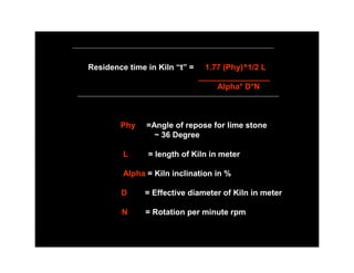
  • 1. Residence time in Kiln “t” = 1.77 (Phy)^1/2 L ________________ Alpha* D*N Phy =Angle of repose for lime stone ~ 36 Degree L = length of Kiln in meter Alpha = Kiln inclination in % D = Effective diameter of Kiln in meter N = Rotation per minute rpm
  • 2. Kiln Kiln Inlet Outlet A B C D E Preheater Zone = 1 min A 7.5m/sec Mat velo Max Precalcination Zone = 2 min B t = 20 -28 = Minutes Calcination Zone = 10-12 min C Burning Zone = 6 – 8 min D 4.5m/sec Cooling Zone = 2 min F Mat Velo Min
  • 3. CLINKERISATION 12 CaO 3Cao.SiO2 (C3S) Lime stone Alite 2 SiO2 2CaO SiO2 (C2S) Silica oxide Belite 1450*C 2 Al2O3 3 CaOAl2O3 (C3A) Aluminium oxide Tricalcium Aluminate Fe2O3 4CaO.Al2O3.Fe2O3 (C4AF) Iron oxide Tetra Calcium Alumino Ferrite
  • 4. LIME SATURATION FACTOR 100* CaO LSF = (2.8 SiO2 + 1.18 Al2O3 + 0.65 Fe2O3) 0.66 > LSF < 1.2 = = AR = > 0.64
  • 5. SILICA RATIO SiO2 SR = (Al2O3 + Fe2O3) 2.2 > SR < 2.6 = =
  • 6. ALUMINA RATIO Al2O3 AR = Fe2O3 1.5 > AR < 2.5 = = AR < 1.5 IS CALLED FERROCEMENTS AR = 0.637 IS CALLED FERRARI CEMENT
  • 7. CALORIFIC VALUE OF COAL LHV = HHV – 50.1H – 5.6 M – 0.191O LHV = LOW HEATING VALUE Kcal /Kg HHV = HIGH HEATING VALUE Kcal /Kg M = % MOISTURE H = % HYDROGEN O = % OXYGEN KCal / Kg x 4.187 x 10^(-3) = MJ/Kg ultimate analysis KCal / Kg x 1.8 = Btu / lb
  • 8. COAL USED IN CEMENT INDUSTRY • LHV = 6500 – 7000 Kcal / Kg • ASH = 12~15 % • VOLATILE MATERIAL = 18~ 22 % • MOISTURE = UP TO 12 %
  • 9. D =Diameter in Meter L = Length in meter WEIGHT OF CYLINDRICAL( kiln) SHELL = W W = Pi x (L) x (D) x thk (mm) x 7.85 Metric Tons
  • 10. THERMAL EXPANSION OF SHELL Skin Temperature Diagram A = Alpha x TxL L= Length of (Kiln) Shell =L1 + L2 Alpha for steel (coefficient of linear expansion = 1.2x 10^ (-5) mm per Meter T= dT =( Average temp – Ambient temp) Degre centigrade L1 L2 A1= (T2a+T1)/2 - T X L1 T2bb A1= (T2b+T1)/2 - T X L2 T1 Ambient temp = T T2a A = A1 +A2
  • 11. IMPOTANT PARAMETERS KILN SPECIFIC VOLUME LOADING = TPD/ m3 or Specific Kiln capacity ~ 2.3 t / m3 at Kiln circumferential speed = 50 cm / sec KILN SPECIFIC THERMAL LOADING = Kcal / m2.hr Specific Kiln thermal loading Qp = 1.4 x 10 ^ 6 x D Kcal / m2. hr Qp should not exceed 3.46 x 10^6 Kcal/m^2.hr COOLER SPECIFIC LOADING or Specific Cooler Capacity = TPD/ m2 = 38 -43 metric ton of clinker per m^2 .24 hr KILN % FILLING = 04 % Min - 16% Max
  • 12. KILN CAPACITY ASSESMENT •Capacity of ID fan. •Preheater cyclone design. •Proclaimed Design & Volume. •Kiln inclination & Volume. •Kiln % filling, Specific volume loading &.Thermal loading. •Kiln Drive capacity. •System Design, Ducts, GCT, fan position & ESP.
  • 13. For Gears: Pitch Diameter = Module x No. of Teeth Blank Diameter = Module x (No of Teeth+2) For Airslide Cloth • Fabric Polyester 100%. • Min=140*C & Max = 260*C. • Permeability = 400m3/hr-m2 or 6m3/min-m2. at 80mbar • Tensile strength : WEFT = 1200 Kg/cm2 : WARP = 600 Kg/cm2 • Air Required = 2.5-3.0(Closed type), (2 Cone silo Bins),(1.5Open Type)
  • 14. PH fan-1 Twin cyclones PH fan-2 Twin cyclones IA IB II III IV Riser Duct V KILN STRING VI V 950*C T.A.Duct SLC PYRO STRING KILN I Girth gear II III
  • 15. CEMENT MILL FORMULAS MILL CRITICAL VELOCITY = 76 / (D)^1/2 MILL ACTUAL VELOCITY = 32 / (D)^1/2
  • 16. D Theta’ Mill charging: Theta H H = 0.16D MILL CROSS SECTION Dynamic Angle of Repose = 35 degree 20 minutes with Horizontal (Theta ) OR Dynamic Angle of Repose = 54 degree 40 minutes with Vertical (Theta )’
  • 17. GRINDING MEDIA LOAD “ G” G = gm.Sy.Pi. (R)^2.L 4 Constants: Sy = specific gravity of G = 4620(R)^2.L ball 7.8-7.9 Ton / m3 gm = Bulk density of charge TAGGARTS FORMULA 4.5 Ton / m3 . Pi = 22/7 or 3.14
  • 18. POWER CONSUMPTION OF MILL = P L= G/D=A-C 2. B-A P= 12G SEPARATOR B%fines/D A %fines/F Seperator efficiency A % fines of separator feed s B % fines of Tailings/Reject C%fine/G C % fines of finished Product F TPH of separator feed D TPH of Tailings/Reject G TPH of finished Product Ball Mill 1. n = C (A-B) 3. A(C-B)) F = L(1+D)
  • 19. L/D=3 Two Compartment Mill L / D = 4.5 Three Compartment Mill I – Chamber Drag Peb Liners Carman Lining Classifying Slegton – Liners Magotteaux Lining Lining FLS Lining
  • 20. Important Conversions 1 Barrel = 42 Gallons = 159 litres = 5.615 Cuft 1 Kcal = 4.187 J KCal / Kg x 1.8 = Btu / lb Characteristic OPC-43(IS8112) OPC-43(IS12269) PPC- (IS1489)Part-1 Blaine 225 225 300 3 Days(MPa) 23 27 16 7 Days 33 37 22 28 Days 43 53 33
  • 21. L H 70 * L=H/2 Length of Dip Tube = ½ Gas inlet height Single Stream
  • 22.
  • 23.
  • 26.
  • 27.
  • 28. Kiln Data : 4.4 meter Diameter x 60 meter length Inclination = 3.5% Shell thicknesses = 25 mm , 28 mm , 35 mm , 65 mm Kiln speed = 3.5 to 5.25 RPM Preheater : Type : 6440 / PR 7044 VI Stage Desc Kiln string Pyro string I Cyclone Twin 4000 m 4400 m (Diameter) 6400 m 7000 m Dip tube 2000 m 2200 m (Diameter) 3200 m 3500 m
  • 29. Girth Gear : Module = 39 No of Teeth = 148 Material of construction = CS 640 (Normalized Cast Steel) Dimensions = 550 mm (width) Pinion : Module = 39 No of Teeth = 28 Material of construction = 30 Cr Ni Mo V8 (Normalized CastSteel) Dimensions = 600 mm (width)
  • 30. Tyre Assemblies three no’s : Material of construction = GS 24 Mn 5 (Normalized Cast Steel) Dimensions = 5620 OD x 4581 ID x 775 (width) Main Drive Supporting Rollers Assemblies three no’s : Material of construction = CS 640 (Normalized Cast Steel) Dimensions = 5620 OD x 4581 ID x 775 (width) Tyre Kiln Supporting Roller Shell Girth Gear Pinion
  • 31. Kiln Main Drive : Gear box = SDN 800 Ratio = 54.35:1 RWN-500 Motor KW = 710 Aux G.B SDA 250 54.35: 1 Input RPM = 100 - 1000 Motor 30 KW ; 1500 RPM Motor G.B G.B Motor RWB-178 Pinion Kiln Axis Concord Alingnomatic Geared Coupling G.G
  • 32.
  • 33.
  • 35.
  • 36. Degree Of Kiln filling & Kiln Cross Sectional loading: % of Filling or Area of this segment (A1) = Kilns Degree Area of cross section of Kiln (A) Theta Centric Angle Theta % of Kiln (Degree) filling 110 15.65 105 13.75 100 12.1 Segment 95 10.7 r = radius inside lining 90 9.09 85 7.75 r^2 A1 = O – Sin O 80 6.52 2 75 5.42 70 4.5 A = II r^2
  • 37. Rotary Kiln Slope versus Load Theta 4.5 4.0 3.5 3.0 2.0 % 9 10 11 12 13 Note : In practical Kiln operation the kiln load should not exceed 13%,since higher Kiln loads impair the heat tranfer Thumb rule by Bohman Material velocity in kiln % Kiln Kiln diameter 1). Burning Zone = 4.5 mm / sec Lowest Slope (m) 5 up to 2.8 m 4 3 m to 3.4 m 2). Calcining Zone = 7.5 mm / sec Max 3 > 3.4 m
  • 38. Rotary Kiln power input calculation : W x bd x td x N x F x 0.0000092 1 H.P = rd W = Total vertical load on all roller shaft bearing,lb bd = roller shaft bearing diameter , inches Note : This is Frictional rd = roller diameter , inches 1 Horse Power td = tire or riding rind diameter , inches N = rpm of Kiln shell P = Coefficient or friction of roller bearings , 0.018 for oil lub bearings & 0.06 for grease lub bearings
  • 39. This is Load Horse 2 Horse Power H.P = (D x Sin O) ^3 x N x L x K 2 D = Kiln dia .inside lining , ft Sin O = read from diagram depending on %Load N = rpm of Kiln shell L = length of kiln in ft K = 0.00076 Total power = 1 + 2
  • 40. Cement Monthly - Edelweiss From: Arun Shourie [mailto:Arun.Shourie@edelcap.com] Arun Shourie Relation Manager - Insurance Dir: +91 (22) 4086 3835 / +91 99200 29366
  • 41. Burner pipe centering location and alignment Burner Pipe Location 40* L v H d D
  • 42. = V Z Cos O D–a–b X K% = Z 2 H = Z Sine O Kiln Diameter = D Kiln lining thickness = a Kiln Coating thickness = b Angle of Repose of kiln load = O = 40* say Kiln Load = K % Value from table below Depth of bed in Kiln = Y % To be measured Kiln load = K % 5 6 7 8 9 10 11 12 13 14 15 Depth of material bed in Kiln = Y % 9.75 11 12.2 13.4 14.5 15.6 16.7 17.7 1.8.8 19.8 21
  • 43. Standard Coal Factor : SCF To determine the approximate combustion air needed to burn a given unit wt of coal, formula given below can be used when no ultimate analysis is available. The combustion air requirement include here 5% of excess air 100 - a B = SCF 100 7000 Kg of Air = 10.478 SCF Kg of Coal a = % Moisture in coal ( as fired ) B = Heat value of coal ( Kcal / kg as fired )
  • 44. % Loading of Kiln : Theoretical Flame Temperature fuel oil : Cxfxt Q T = L = Vg x Cp dxV Q = heating value of oil , K cal / kg C = Capacity of Kiln Ton / hr Vg = Volume of combustion gases , f = Ton (Kg) dry feed / Ton ( kg) of Clinker Nm^3 / Kg t = residence time Cp = Specific heat of d = Bulk density of dry feed ton (Kg) / m^3 combustion gases =0.40 at 2000*C for V = Internal volume of kiln in m^3 fuel class “S”
  • 45. Rotary kiln Capacity Martin’s Formula : C = 2.826 v X D^3 Vg C = Kiln Capacity Ton / Hr V = Gas Velocity in gas discharge end , m / sec Vg = specific gas volume , m^3 / kg clinker D = Kiln Diameter on Bricks, m
  • 46. Heat capacity of Rotary kiln 1 Q = 1.1 x 10 ^ 6 x D ^3 (Kcal / hr) D = Mean inside Kiln Diameter on Bricks, m 2 Kiln Thermal loading at cross section of burning zone = Qp = = Q / Fp Fp = 0.785 x D^2 Inside cross-section of the kiln burning zone m^2 where D is kiln shell diameter Q p = 1.4 x 10 ^ 6 x D Kcal / m^2.hr Qp should not exceed 3.46 x 10 ^ 6 kcal / m2.hr
  • 47. Heat transfer in cyclones preheater: The rule is that the sizes of the gas ducts and of the cyclone should be in accordance with the formula: V^2 = Constant ID ^ 5 V = Gas volume ID = Inside Diameter of ducts / cyclones respectively
  • 48. Preheater cyclone sizing (V) ^ 2 x Vt C D = 0.536 4 P Vt = V0 273 + t + K K = dust concentration in Gas , grams / m^ 3 273 D = cyclone Diameter , m V = Gas volume passimg cyclone , m ^ 3 / Sec Vt = sp. gr. of gas at aver. Temp , Kg / m ^ 3 C = Coefficient for pressure drop = 110 P = Pressure drop in cyclone in mm WG
  • 49. Small size high efficiency cyclone L H 70 * L=H/2 Length of Dip Tube = ½ Gas inlet height Single Stream Pressure drop across cyclone = 55 – 60 mbar
  • 50. Theoretical Heat consumption Q for clinker burning :zur Strassen formula : Constituent Constituent Multiplication Heat Cons Net Name X % Factor Y kcal/kg Al2O3 5.92 2.22 + 13.1 + MgO 1.05 6.48*MgO6.48 + 6.8 527.4 CaO 63.91 7.646 + 488.7 H2O 3.2 5.86 + 18.8 _ SiO2 22.68 5.11 _ 117 118.4 Fe2O3 2.31 0.59 _ 1.4 Net % 99.27 Net Kcal / Kg = 409.0 Q = 2.22 Al203 + 6.48 MgO + 7.646 CaO + 5.86 H2O + 5.11 SiO2 + 0.59 Fe2O3
  • 51. Thermal efficiency of cooler = E A-B X 100 E= A A = Heat loss of clinker leaving the kiln B = Heat loss of the clinker cooler 3250 (347 – K ) Secondary Air Temperature = t = (X.n) K = Heat loss of the cooler , Kcal/Kg clinker X = Specific Heat consumption of the kiln , Kcal / Kg clinker n = Excess Air number = 1.1 Cooler fans designed for Specific Volume of 3 – 3.15 st.m^3/Kg clinker
  • 52. Cooling of kiln Exit Gases (GCT) Kg / min.Exit gas x 0.25 ( t 1 – t 2) Kcal / min Y= H t2 – H t3 t1 = Temperature of Kiln exit gases t2 = Temperature of gas to be achieved or maitained t3 = temperature of water (15*C) H t2 = Heat content of water at t2 H t3 = Heat content of water at t3 Y = Kg Water Spray / min