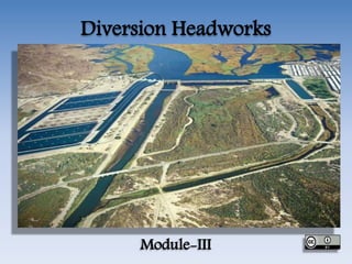
SlideShare ist ein Scribd-Unternehmen logo
1 von 108
Diversion Headworks
Module-III
• Diversion Headworks:
• Types- selection of the suitable site for the
diversion headwork- components of diversion
headwork- Causes of failure of structure on
pervious foundation- Khosla’s theory- Design
of concrete sloping glacis weir
Diversion Head-Works
• The works which are constructed at the head
of the canal in order to divert the river water
toward the canal, so as to ensure a regulated
continuous supply mostly silt free water with
certain minimum head into the canal, are
known as diversion headworks.
Diversion Head-Works
Objectives of Diversion Head Works
• The Following are the objective of Diversion
Head works
• To Raise the water level at the head of canal.
• To form a storage by construction of dykes on
both side of banks of the river so that water is
available throughout the year.
• To control the entry of silt into the canal and to
control the deposition of silt at the head of canal.
• To control the fluctuation of water level in the
river during different seasons.
Objective of Diversion Head works
Selection of Site for Diversion Head
Works
• The following points should be considered to
select a site for this diversion headworks.
• The river should be straight and narrow at the
site
• The elevation of site should be higher than the
area to be irrigated for gravity flow.
• River banks at site should be well defined and
stable.
• Valuable land upstream of the barrier like
weir or barrage should not be submerged.
Selection of Site for Diversion Head
Works
• Material of construction should be locally
available.
• Roads or railway communication to the site is
essential to carry the material of construction.
• Site should be close to the cropland to
minimize loss of water due to seepage and
evaporation of canal.
• The site should provide a good foundation for
construction of weir or barrage.
Selection of Site for Diversion Head
Works
Components of Diversion Headworks
• The components of diversion headworks are:
• Weir or barrage
• Canal head regulator
• Divide Wall
• Fish Ladder
• Scouring Sluices Under sluices
• Silt excluder
• Silt ejector.
• Marginal embankment or dikes
• Guide bank
• Silt pocket or trap.
Weir or Barrage
• Weir is a solid obstruction placed across the
river. Its main function is to raise the water
level so that water can be diverted by canal to
crop field due to difference of head.
• Barrage is practically a low weir with an
adjustable gate over this low weir. Heading up
of water is affected by gate.
Weir
Weir
Weir
Barrage
Barrage
Barrage
Comparison Between Weir & a
Barrage
Types of Weir
Types of Weir
• Weir may be of different types based on material of
construction, design features and types of soil
foundation as:
• Vertical Drop Weir
• A crest gate may be provided to store more water
during flood period. At the upstream and downstream
ends of impervious floor cut off piles are provided.
Launching apron are provided both at upstream and
downstream ends of floor to safeguard against
scouring action. A graded filter is provided
immediately at the downstream end of impervious
floor to relieve the uplift pressure. This type of weir is
suitable for any type of foundation.
Vertical Drop Weir
Vertical Drop Weir
Vertical Drop Weir
Types of Weir
• Sloping Weir of Concrete:
• This type is suitable for soft sandy foundation.
It is used where difference in weir crest and
downstream riverbed is not more than 3 m.
Hydraulic jump is formed when water passes
over the sloping glacis. Weir of this type is of
recent origin.
Sloping Weir of Concrete
Types of Weir
• Parabolic Weir:
• A parabolic weir is almost similar to spillway
section of dam. The weir body wall for this
weir is designed as low dam. A cistern is
provided at downstream.
Types of Weir
Types of Weir
• Dry Stone Slopping Weir:
• It is dry stone or rock fill weir. It consists of
body wall and upstream and downstream dry
stones are laid in the form of glacis with some
intervening core wall.
Dry Stone Slopping Weir
Barrage
• When the water level on the upstream side of
the weir is required to be raised to different
levels at different time, then the barrage is
constructed. Practically a barrage is an
arrangement of adjustable gates or shutters at
different tiers over the weir. The water level
can be adjusted by the opening of gates.
Barrage
Divide Wall
• The Divide Wall is a long wall constructed at right angle to the
weir or barrage, it may be constructed with stone masonry or
cement concrete. On the upstream side, the wall is extended
just to cover the canal regulator and on the down stream side,
it is extended up to the launching apron. The functions of the
divide wall are as follows,
• (a) To form a still water pocket in front of the canal head so
that the suspended silt can be settled down which then later
can be cleared through the scouring sluices from time to time.
• (b) It controls the eddy current or cross current in front of the
canal head.
• (c) It provides a straight approach in front of the canal head.
• (d) It resists the overturning effect on the weir or barrage
caused by the pressure of the impounding water.
Divide Wall
Scouring Sluices or Under Sluices
• The Scouring sluices are the openings provided
at the base of the weir or barrage. These
openings are provided with adjustable gates.
Normally, the gates are kept closed. The
suspended silt goes on the depositing in front of
the canal head regulator. When the silt
deposition becomes appreciable the gates are
opened and the deposited silt is loosened with an
agitator mounting on a boat. The muddy water
flows towards the downstream side through the
scouring sluices. The gates are closed. But, at the
period of flood, the gates are kept opened.
Under Sluices
Scouring Sluices or Under Sluices
Fish Ladder
• The Fish Ladder is provided just by the side of the
divide wall for the movement of fishes. Rivers are
important source of fishes. There are various types of
fish in the river. The nature of fish varies from type
to type. But in general, the tendency of fish is to
move from upstream to downstream in winters and
from downstream to upstream in monsoons. This
movement is essential for their survival.
Fish Ladder
• Due to construction of weir or barrage, this
movement gets obstructed, and is detrimental to
the fishes. For the movement of the fishes along
the course of the river, the fish ladder is essential.
In the fish ladder, the baffle walls are
constructed in the zigzag manner so that the
velocities of flow within the ladder does not
exceed 3 m/s. The width, length, and height of
the fish ladder depends on the nature of the river
and the type of the weir or barrage.
Fish Ladder
Fish Ladder
Canal Head Regulator
• A structure which is constructed at the head of
the canal regulator to regulate the flow of water
is known as canal head regulator. It consists of a
number of piers which divide the total width of
the canal into a number of spans which are
known as bays. The pier consists of a number of
tiers on which the adjustable gates are placed.
The gates are operated from the top by suitable
mechanical device. A platform is produced on
the top of the piers for the facility of operating
the gates. Again some piers are constructed on
the downstream side of the canal head to support
the roadway.
Canal Head Regulator
Silt Excluder
• When still pocket is formed in front of the canal
head by constructing the divide wall, then it is found
that the lower layer of water contains heavy silt and
the upper layer contains very fine silt. The fine silt is
very fertile and it may be allowed to enter the canal.
But the heavy silt causes sedimentation in the
pocket.. To eliminate the suspended heavy silt, the
silt excluder is provided. It consists of a series of
tunnels starting from the side of the head regulator
up to the divide wall.
Silt Excluder
• The tunnel nearest to the head regulator is
longest, and the successive tunnels decrease in
length, the tunnel nearest to the divide wall is
shortest. The tunnels are covered by R.C.C. Slab.
The top level of the slab is kept below the sill
level of the head regulator. So, the completely
clear water is allowed to flow in the canal
through the head regulator. The suspended
heavy silt carried by the water enters the silt
excluder tunnels and passes out through the
scouring sluices.
Silt Excluder
• Silt excluders are those works which are
constructed on the bed of the river, upstream
of the head regulator. The clearer water
enters the head regulator and silted water
enters the silt excluder. In this type of
works, the silt is, therefore, removed from the
water before in enters the canal.
Silt Excluder
Silt Ejectors
• Silt ejectors, also called silt extractors, are
those devices which extract the silt from
the canal water after the silted water has
• traveled a certain distance in the off-take
canal. These works are, therefore, constructed
on the bed of the canal, and little distance
downstream from the head regulator.
Silt Ejectors
Marginal Embankments or dykes
• The marginal embankments or dykes are earthen
embankments which are constructed parallel to the
river bank on one or both the banks according to the
condition. The top width is generally 3 to 4 m and side
slope is generally 1 ½ : 1 to 2: 1. The height of the
embankment depends on the highest flood level. A
suitable margin is provided between the toe of the
embankment and the bank of the river. To resist the
effect of erosion on the embankment, wooden piles are
driven along the river banks throughout the length of
dyke. The length of the dyke is protected by boulders
pitching with cement grouting and the downstream
side is protected by turfing.
Marginal Embankments or dykes
• The Marginal Bunds are constructed for the
following purposes.
• (a) It prevents the flood water or storage
water from entering the surrounding area.
• (b) It retains the flood water or storage water
within a specified section.
• (c) It Protects the towns and village from
devastation during the heavy flood.
• (d) It protects valuable agricultural lands.
Marginal Embankments
Guide Bank
• When a barrage is constructed across a river which
flows through the alluvial soil, the guide banks must
be constructed on both the approaches to protect the
structure from erosion. It is an earthen embankment
with curved head on both the ends.
• The Guide Bank serves the following purposes.
• It protects the barrage from the effect of scouring and
erosion.
• It controls the tendency of changing the course of the
river.
• It controls the velocity of the flow near the structure.
Guide Bank
Guide Bank
Guide Bank
• Components of Guide Banks are
• Upstream curved head
• Downstream curved head
• Shank portion which joins upstream and
downstream curved end
• Sloping apron
• Launching apron
• Pile protection
Guide Bank
Causes of Failure of weir or barrage
on permeable foundation
• The combined effect of surface flow and surface flow may
cause the failure of the weir or barrage.
• (i) Failure due to subsurface flow
• (a) By piping or undermining: The water from the
upstream side continuously percolates through the bottom
of the foundation and emerges at the downstream end of
the weir or barrage floor. The force of percolating water
removes the soil particles by scouring at the point of
emergence. As the process of removal of soil particles goes
on continuously, a depression is formed which extends
backwards towards the upstream through the bottom of
the foundation. A hollow pipe like formation thus develops
under the foundation due to which the weir or barrage
may fail by subsiding. This phenomenon is known as
failure by piping or undermining.
By Piping or Undermining
Causes of Failure of weir or barrage
on permeable foundation
• (b) By uplift Pressure: The percolating water exerts an upward pressure
on the foundation of the weir or barrage. If this uplift is not
counterbalanced by the self weight of the structure, it may fail by
rapture.
• 2. Failure by Surface Flow:
• (a) By Hydraulic Jump: When the water flows with a very high velocity
over the crust of the weir or over the gates of the barrage, then
hydraulic jump develops. This hydraulic jump causes a suction
pressure or negative pressure on the downstream side which acts in
the direction of uplift pressure. If the thickness of the impervious floor
is not sufficient, then the structure fails by rapture.
• (b) By Scouring During floods: The gates of the barrage are kept open
and the water flows with high velocity. The water may also flow with
very high velocity over the crest of the weir. Both the cases can result
in scouring effect on the downstream and on the upstream side of the
structure. Due to scouring effect on the downstream and on the
upstream side of the structure, its stability gets endangered by shearing.
By Uplift Pressure
By Hydraulic Jump
By Scouring During floods
Causes of Failure of Weir, and
Remedies
• If a weir is constructed on permeable soil, weir may fail
by piping, uplift force, suction caused by standing wave
and scouring on both upstream and downstream of the
weir.
• When hydraulic gradient or exit gradient exceeds the
critical value of soil, surface soil at down end starts
boiling first and is washed away by percolating water.
This process of removal or washing out of soil continuous
and eventually a channel in the form of pipe is formed by
seepage water. This is called piping which may cause the
failure of foundation. Similarly uplift force of percolating
water is acting on ther floor from bottom and if the
weight of floor is not enough to resist this uplift force,
floor may fail by cracking or bursting.
Causes of Failure of Weir, and
Remedies
• The main remedies against failure are:
• Path of percolation or creep length of seepage
water should be increased by providing sheet
piles at upstream, downstream or at
intermediate point to reduce the hydraulic
gradient.
• Floor thickness should be increased to
increase its self weight to balance the uplift
force.
Precautions Against Failure
• The following precautions can be taken to prevent
failure.
• (a) The length of the impervious layer should be
carefully designed so that the path of the percolating
water is increased consequently reducing the exit
gradient.
• (b) Sheet piles should be provided on the upstream
side and the downstream side of the impervious
floor to increase to the length of percolating water
so that the uplift pressure is considerable reduced.
• (c) The thickness of the impervious floor should be
such that the weight of the floor is a sufficient to
counterbalance the uplift pressure.
Precautions Against Failure
• (d) Energy dissipater blocks like friction
blocks, impact blocks, should be provided.
• (e) Inverted filter should be provided with
concrete blocks on the top so that the
percolating water does not wash out the soil
particles.
• Deep foundation like well foundation should
be provided for the barrage piers
Precautions Against Failure
Energy Dissipater Blocks
Increasing Floor
Thickness
Flow Net
• A flownet is a graphical representation of two-
dimensional steady-state groundwater flow
through aquifers.
• The method consists of filling the flow area with
stream lines and equipotential lines, which are
everywhere perpendicular to each other, making
a curvilinear grid.
• Stream Lines: The streamlines represent the paths
along which the water flows through the sub-soil.
• Equipotential lines: Equipotential lines are lines of
• equal hydraulic head.
Flow Net
Khosla’s Theory
• Khosla’s Theory and Concept of Flow Nets
• Many of the important hydraulic structures,
such as weirs and barrage, were designed on
the basis of Bligh’s theory between the periods
1910 to 1925. In 1926 – 27, the upper Chenab
canal siphons, designed on Bligh’s theory,
started posing undermining troubles.
Investigations started, which ultimately lead to
• Khosla’s theory. The main principles of this theory
are summarized below:
• (a) The seepage water does not creep along the
bottom contour of pucca flood as started by Bligh,
but on the other hand, this water moves along a set
of stream-lines. This steady seepage in a vertical
plane for a homogeneous soil can be expressed by
Laplacian equation:
Khosla’s Theory
• The equation represents two sets of curves
intersecting each other orthogonally. The resultant
flow diagram showing both of the curves is called a
Flow Net.
• Stream Lines: The streamlines represent the paths
along which the water flows through the sub-soil.
• Every particle entering the soil at a given point
upstream of the work, will trace out its own path and
will represent a streamline. The first streamline
follows the bottom contour of the works and is the
same as Bligh’s path of creep. The remaining
streamlines follows smooth curves transiting slowly
from the outline of the foundation to a semi-ellipse, as
shown below.
Khosla’s Theory
• Equipotential Lines: (1) Treating the downstream bed
as datum and assuming no water on the downstream
side, it can be easily started that every streamline
possesses a head equal to h1 while entering the soil;
and when it emerges at the down-stream end into the
atmosphere, its head is zero. Thus, the head h1 is
entirely lost during the passage of water along the
streamlines.
Khosla’s Theory
• Further, at every intermediate point in its path,
there is certain residual head (h) still to be dissipated
in the remaining length to be traversed to the
downstream end. This fact is applicable to every
streamline, and hence, there will be points on
different streamlines having the same value of
residual head h. If such points are joined together,
the curve obtained is called an equipotential line.
Khosla’s Theory
Khosla’s Theory
Every water particle on line AB is having a
residual head h = h1, and on CD is having a
residual head h = 0, and hence, AB and CD
are equipotential lines.
Since an equipotential line represent the
joining of points of equal residual head, hence
if piezometers were installed on an
equipotential line, the water will rise in all of
them up to the same level as shown in figure
below
Khosla’s Theory
Khosla’s Theory
• The seepage water exerts a force at each point in the
direction of flow and tangential to the streamlines as
shown in figure above. This force (F) has an upward
component from the point where the streamlines turns
upward. For soil grains to remain stable, the upward
component of this force should be counterbalanced by
the submerged weight of the soil grain. This force has
the maximum disturbing tendency at the exit end,
because the direction of this force at the exit point is
vertically upward, and hence full force acts as its
upward component.
Khosla’s Theory
• For the soil grain to remain stable, the
submerged weight of soil grain should be more
than this upward disturbing force. The
disturbing force at any point is proportional to
the gradient of pressure of water at that point
(i.e. dp/dt). This gradient of pressure of water at
the exit end is called the exit gradient. In order
that the soil particles at exit remain stable, the
upward pressure at exit should be safe. In other
words, the exit gradient should be safe.
Critical Exit Gradient
• This exit gradient is said to be critical, when
the upward disturbing force on the grain is
just equal to the submerged weight of the
grain at the exit. When a factor of safety equal
to 4 to 5 is used, the exit gradient can then be
taken as safe. In other words, an exit gradient
equal to ¼ to 1/5 of the critical exit gradient
ensured, so as to keep the structure safe
against piping.
• The submerged weight (Ws) of a unit volume
of soil is given as:
Critical Exit Gradient
Khosla’s Method of independent variables for
determination of pressures and exit gradient for
seepage below a weir or a barrage
• In order to know as to how the seepage below the
foundation of a hydraulic structure is taking place, it is
necessary to plot the flow net. In other words, we must
solve the Laplacian equations. This can be
accomplished either by mathematical solution of the
Laplacian equations, or by Electrical analogy method,
or by graphical sketching by adjusting the streamlines
and equipotential lines with respect to the boundary
conditions. These are complicated methods and are
time consuming. Therefore, for designing hydraulic
structures such as weirs or barrage or pervious
foundations, Khosla has evolved a simple, quick and an
• accurate approach, called Method of Independent
Variables.
Khosla’s Method of independent variables for
determination of pressures and exit gradient for
seepage below a weir or a barrage
• In this method, a complex profile like that of a weir is
broken into a number of simple profiles; each of
which can be solved mathematically. profiles which
are most useful are:
• (i) A straight horizontal floor of negligible thickness
with a sheet pile line on the u/s end and d/s end.
• (ii) A straight horizontal floor depressed below the bed
but without any vertical cut-offs.
• (iii) A straight horizontal floor of negligible thickness
with a sheet pile line at some intermediate point.
Khosla’s Method of independent variables for
determination of pressures and exit gradient for
seepage below a weir or a barrage
• The key points are the junctions of the floor and the
pole lines on either side, and the bottom point of
• the pile line, and the bottom corners in the case of a
depressed floor. The percentage pressures at these key
• points for the simple forms into which the complex
profile has been broken is valid for the complex
profile
• itself, if corrected for
• (a) Correction for the Mutual interference of Piles
• (b) Correction for the thickness of floor
• (c) Correction for the slope of the floor
(a) Correction for the Mutual interference of
Piles
The correction C to be applied as percentage of head due to this effect, is given
by
Where,
b′ = The distance between two pile lines.
D = The depth of the pile line, the influence of which has to be determined on
the neighboring pile of depth d. D is to be measured below the level at
which interference is desired.
d = The depth of the pile on which the effect is considered
b = Total floor length
The correction is positive for the points in the rear of back water, and
subtractive for the points forward in the direction of flow. This equation
does not apply to the effect of an outer pile on an intermediate pile, if the
intermediate pile is equal to or smaller than the outer pile and is at a
distance less than twice the length of the outer pile.
(a) Correction for the Mutual interference of
Piles
(a) Correction for the Mutual interference of
Piles
• Suppose in the above figure, we are considering the influence of
the pile no (2) on pile no (1) for correcting the pressure at C1.
Since the point C1 is in the rear, this correction shall be positive.
While the correction to be applied to E2 due to pile no (1)
shall be negative, since the point E2 is in the forward direction
of flow. Similarly, the correction at C2 due to pile no (3) is
positive and the correction at E2 due to pile no (2) is negative.
(b) Correction for the Thickness of Floor
• In the standard form profiles, the floor is
assumed to have negligible thickness. Hence,
the percentage pressures calculated by
Khosla’s equations or graphs shall pertain to
the top levels of the floor. While the actual
junction points E and C are at the bottom of
the floor. Hence, the pressures at the actual
points are calculated by assuming a straight
line pressure variation.
(b) Correction for the thickness of floor
• Correction for the slope of the floor a correction is applied for
a slopping floor, and is taken as positive for the downward
slopes, an negative for the upward slopes following the
direction of flow. Values of correction of standard slop such
as 1 : 1, 2 : 1, 3 : 1, etc. are tabulated in Table below
(b) Correction for the thickness of floor
• The correction factor given above is to be multiplied
by the horizontal length of the slope and divided by
the distance between the two pile lines between
which the sloping floor is located. This correction is
applicable only to the key points of the pile line fixed
at the start or the end of the slope.
Exit gradient (GE)
• It has been determined that for a standard form
consisting of a floor length (b) with a vertical cutoff
of depth (d), the exit gradient at its downstream end
is given by
Important Questions
• Explain Khosla’s method of independent variables.
• Explain the term ”Diversion Head Work” and
clearly mention its different functions.
• Explain Bligh’s Creep Theory in details.
• What is weir? How does it differ from a barrage
structure?
• What are the functions of a canal head regulator?
Reference
• Irrigation Engineering : N.N. Basak
• Irrigation Engineering & Hydraulic
Structures: S.K.Garg
• Internet Websites
Thanks
GHT

Weitere ähnliche Inhalte

Was ist angesagt? (20)

Canal lining
Canal liningCanal lining
Canal lining
 
Diversion headworks
Diversion headworksDiversion headworks
Diversion headworks
 
Canal alignment
Canal alignmentCanal alignment
Canal alignment
 
Diversion head works
Diversion head worksDiversion head works
Diversion head works
 
Canal
CanalCanal
Canal
 
Gravity dam
Gravity damGravity dam
Gravity dam
 
river training work
river training workriver training work
river training work
 
Design of Canal (Kennedy & Lacey Theory) & Diversion Headwork
Design of Canal (Kennedy & Lacey Theory) & Diversion HeadworkDesign of Canal (Kennedy & Lacey Theory) & Diversion Headwork
Design of Canal (Kennedy & Lacey Theory) & Diversion Headwork
 
Energy dissipation - irrigation engineering
Energy dissipation - irrigation engineeringEnergy dissipation - irrigation engineering
Energy dissipation - irrigation engineering
 
Stilling basin
Stilling basinStilling basin
Stilling basin
 
Spillway gates
Spillway gatesSpillway gates
Spillway gates
 
Failure of weir and barrage
Failure of weir and barrageFailure of weir and barrage
Failure of weir and barrage
 
Canal of design
Canal of designCanal of design
Canal of design
 
Intake structures-Introduction
Intake structures-IntroductionIntake structures-Introduction
Intake structures-Introduction
 
Kennedy's and laccy's theory
Kennedy's and laccy's theoryKennedy's and laccy's theory
Kennedy's and laccy's theory
 
Reservoir Planning
Reservoir PlanningReservoir Planning
Reservoir Planning
 
Reservior planning
Reservior    planningReservior    planning
Reservior planning
 
Dams and spillways
Dams and spillwaysDams and spillways
Dams and spillways
 
Regulation Works
Regulation WorksRegulation Works
Regulation Works
 
Earthen Dams
Earthen DamsEarthen Dams
Earthen Dams
 

Ähnlich wie Diversion Headworks

Presentation1 hydro;ogy-SKK.pdf
Presentation1 hydro;ogy-SKK.pdfPresentation1 hydro;ogy-SKK.pdf
Presentation1 hydro;ogy-SKK.pdfShrutiLotliker
 
Diversion of headwork
Diversion of headwork Diversion of headwork
Diversion of headwork Jay Khoradiya
 
DIVERSION HEAD WORKS
DIVERSION HEAD WORKSDIVERSION HEAD WORKS
DIVERSION HEAD WORKSMood Naik
 
Design of Hydraulic Structures
Design of Hydraulic StructuresDesign of Hydraulic Structures
Design of Hydraulic StructuresDamalla Rams
 
Ce 413 hydraulic structures 8th
Ce 413 hydraulic structures 8thCe 413 hydraulic structures 8th
Ce 413 hydraulic structures 8thEngrHayatHussain
 
MODULE 4 REGULATING AND CROSS DRAINAGE WORKS.pptx
MODULE 4 REGULATING AND CROSS DRAINAGE WORKS.pptxMODULE 4 REGULATING AND CROSS DRAINAGE WORKS.pptx
MODULE 4 REGULATING AND CROSS DRAINAGE WORKS.pptxSilasChaudhari
 
Design of hydraulic structures ce 413
Design of hydraulic structures ce 413Design of hydraulic structures ce 413
Design of hydraulic structures ce 413Saqib Imran
 
UNIT 5 Distribution Works.pptx
UNIT 5 Distribution Works.pptxUNIT 5 Distribution Works.pptx
UNIT 5 Distribution Works.pptxDivs97
 
Canal MASONRY WORK
Canal MASONRY WORKCanal MASONRY WORK
Canal MASONRY WORKSAGAR RAUT
 
Diversionheadworkm3 120625052707-phpapp02
Diversionheadworkm3 120625052707-phpapp02Diversionheadworkm3 120625052707-phpapp02
Diversionheadworkm3 120625052707-phpapp02saibabu48
 
Diversion head work
Diversion head workDiversion head work
Diversion head workdhruvalsu
 
Diversion Headwork in Canal
 Diversion Headwork in Canal  Diversion Headwork in Canal
Diversion Headwork in Canal holegajendra
 

Ähnlich wie Diversion Headworks (20)

Diversion head work
Diversion head workDiversion head work
Diversion head work
 
Presentation1 hydro;ogy-SKK.pdf
Presentation1 hydro;ogy-SKK.pdfPresentation1 hydro;ogy-SKK.pdf
Presentation1 hydro;ogy-SKK.pdf
 
Diversion of headwork
Diversion of headwork Diversion of headwork
Diversion of headwork
 
DIVERSION HEAD WORK
DIVERSION HEAD WORKDIVERSION HEAD WORK
DIVERSION HEAD WORK
 
DIVERSION HEAD WORKS
DIVERSION HEAD WORKSDIVERSION HEAD WORKS
DIVERSION HEAD WORKS
 
Design of Hydraulic Structures
Design of Hydraulic StructuresDesign of Hydraulic Structures
Design of Hydraulic Structures
 
Ce 413 hydraulic structures 8th
Ce 413 hydraulic structures 8thCe 413 hydraulic structures 8th
Ce 413 hydraulic structures 8th
 
Diversion head works
Diversion head worksDiversion head works
Diversion head works
 
Diversion headworks
Diversion headworksDiversion headworks
Diversion headworks
 
MODULE 4 REGULATING AND CROSS DRAINAGE WORKS.pptx
MODULE 4 REGULATING AND CROSS DRAINAGE WORKS.pptxMODULE 4 REGULATING AND CROSS DRAINAGE WORKS.pptx
MODULE 4 REGULATING AND CROSS DRAINAGE WORKS.pptx
 
Design of hydraulic structures ce 413
Design of hydraulic structures ce 413Design of hydraulic structures ce 413
Design of hydraulic structures ce 413
 
Diversion headworks
Diversion headworksDiversion headworks
Diversion headworks
 
UNIT 5 Distribution Works.pptx
UNIT 5 Distribution Works.pptxUNIT 5 Distribution Works.pptx
UNIT 5 Distribution Works.pptx
 
Canal MASONRY WORK
Canal MASONRY WORKCanal MASONRY WORK
Canal MASONRY WORK
 
Diversionheadworkm3 120625052707-phpapp02
Diversionheadworkm3 120625052707-phpapp02Diversionheadworkm3 120625052707-phpapp02
Diversionheadworkm3 120625052707-phpapp02
 
Lecture 8
Lecture 8Lecture 8
Lecture 8
 
Diversion head work
Diversion head workDiversion head work
Diversion head work
 
Diversion Headwork in Canal
 Diversion Headwork in Canal  Diversion Headwork in Canal
Diversion Headwork in Canal
 
Ch-3.pptx
Ch-3.pptxCh-3.pptx
Ch-3.pptx
 
Diversion Headworks
Diversion HeadworksDiversion Headworks
Diversion Headworks
 

Mehr von GAURAV. H .TANDON

Suicide Prevention through Architecture (Building) and City Planning
Suicide Prevention through  Architecture (Building) and City PlanningSuicide Prevention through  Architecture (Building) and City Planning
Suicide Prevention through Architecture (Building) and City PlanningGAURAV. H .TANDON
 
Suicide Prevention through Architecture (Building) and City Planning
Suicide Prevention through  Architecture (Building) and City PlanningSuicide Prevention through  Architecture (Building) and City Planning
Suicide Prevention through Architecture (Building) and City PlanningGAURAV. H .TANDON
 
Digital Detoxing in Smart Cities
Digital Detoxing in Smart CitiesDigital Detoxing in Smart Cities
Digital Detoxing in Smart CitiesGAURAV. H .TANDON
 
Digital Detoxing in Smart Cities
Digital Detoxing in Smart CitiesDigital Detoxing in Smart Cities
Digital Detoxing in Smart CitiesGAURAV. H .TANDON
 
Crash for Cash-Organized Crime (COC).pptx
Crash for Cash-Organized Crime (COC).pptxCrash for Cash-Organized Crime (COC).pptx
Crash for Cash-Organized Crime (COC).pptxGAURAV. H .TANDON
 
Ecological Footprint (1).pptx
Ecological Footprint (1).pptxEcological Footprint (1).pptx
Ecological Footprint (1).pptxGAURAV. H .TANDON
 
The unethical practice of gift giving to doctors by pharma companies
The unethical practice of gift giving to doctors by pharma companiesThe unethical practice of gift giving to doctors by pharma companies
The unethical practice of gift giving to doctors by pharma companiesGAURAV. H .TANDON
 
Gamification of Smart Cities
Gamification of Smart Cities Gamification of Smart Cities
Gamification of Smart Cities GAURAV. H .TANDON
 
Collusion and Fraud Detection on Electronic Energy Meters
Collusion and Fraud Detection on Electronic Energy Meters Collusion and Fraud Detection on Electronic Energy Meters
Collusion and Fraud Detection on Electronic Energy Meters GAURAV. H .TANDON
 
Cyber Security in Smart Buildings
Cyber Security in Smart Buildings Cyber Security in Smart Buildings
Cyber Security in Smart Buildings GAURAV. H .TANDON
 

Mehr von GAURAV. H .TANDON (20)

Suicide Prevention through Architecture (Building) and City Planning
Suicide Prevention through  Architecture (Building) and City PlanningSuicide Prevention through  Architecture (Building) and City Planning
Suicide Prevention through Architecture (Building) and City Planning
 
Suicide Prevention through Architecture (Building) and City Planning
Suicide Prevention through  Architecture (Building) and City PlanningSuicide Prevention through  Architecture (Building) and City Planning
Suicide Prevention through Architecture (Building) and City Planning
 
Digital Detoxing in Smart Cities
Digital Detoxing in Smart CitiesDigital Detoxing in Smart Cities
Digital Detoxing in Smart Cities
 
Digital Detoxing in Smart Cities
Digital Detoxing in Smart CitiesDigital Detoxing in Smart Cities
Digital Detoxing in Smart Cities
 
Premerital Sceening .pptx
Premerital Sceening .pptxPremerital Sceening .pptx
Premerital Sceening .pptx
 
Polymath(Renaissance man)
Polymath(Renaissance man)Polymath(Renaissance man)
Polymath(Renaissance man)
 
Crash for Cash-Organized Crime (COC).pptx
Crash for Cash-Organized Crime (COC).pptxCrash for Cash-Organized Crime (COC).pptx
Crash for Cash-Organized Crime (COC).pptx
 
Voting Age .pptx
Voting Age .pptxVoting Age .pptx
Voting Age .pptx
 
Ecological Footprint (1).pptx
Ecological Footprint (1).pptxEcological Footprint (1).pptx
Ecological Footprint (1).pptx
 
Urban Heat Island Effect
Urban Heat Island EffectUrban Heat Island Effect
Urban Heat Island Effect
 
Communication Skills
Communication SkillsCommunication Skills
Communication Skills
 
The unethical practice of gift giving to doctors by pharma companies
The unethical practice of gift giving to doctors by pharma companiesThe unethical practice of gift giving to doctors by pharma companies
The unethical practice of gift giving to doctors by pharma companies
 
Compassionate Cities
Compassionate CitiesCompassionate Cities
Compassionate Cities
 
Gamification of Smart Cities
Gamification of Smart Cities Gamification of Smart Cities
Gamification of Smart Cities
 
Anti-Microbial Copper
Anti-Microbial Copper Anti-Microbial Copper
Anti-Microbial Copper
 
Smart Forest City
Smart Forest City Smart Forest City
Smart Forest City
 
Smart forest cities
Smart forest cities Smart forest cities
Smart forest cities
 
Automotive Hacking
Automotive Hacking Automotive Hacking
Automotive Hacking
 
Collusion and Fraud Detection on Electronic Energy Meters
Collusion and Fraud Detection on Electronic Energy Meters Collusion and Fraud Detection on Electronic Energy Meters
Collusion and Fraud Detection on Electronic Energy Meters
 
Cyber Security in Smart Buildings
Cyber Security in Smart Buildings Cyber Security in Smart Buildings
Cyber Security in Smart Buildings
 

Kürzlich hochgeladen

Mine Environment II Lab_MI10448MI__________.pptx
Mine Environment II Lab_MI10448MI__________.pptxMine Environment II Lab_MI10448MI__________.pptx
Mine Environment II Lab_MI10448MI__________.pptxRomil Mishra
 
CS 3251 Programming in c all unit notes pdf
CS 3251 Programming in c all unit notes pdfCS 3251 Programming in c all unit notes pdf
CS 3251 Programming in c all unit notes pdfBalamuruganV28
 
Computer Graphics Introduction, Open GL, Line and Circle drawing algorithm
Computer Graphics Introduction, Open GL, Line and Circle drawing algorithmComputer Graphics Introduction, Open GL, Line and Circle drawing algorithm
Computer Graphics Introduction, Open GL, Line and Circle drawing algorithmDeepika Walanjkar
 
Artificial Intelligence in Power System overview
Artificial Intelligence in Power System overviewArtificial Intelligence in Power System overview
Artificial Intelligence in Power System overviewsandhya757531
 
Input Output Management in Operating System
Input Output Management in Operating SystemInput Output Management in Operating System
Input Output Management in Operating SystemRashmi Bhat
 
Novel 3D-Printed Soft Linear and Bending Actuators
Novel 3D-Printed Soft Linear and Bending ActuatorsNovel 3D-Printed Soft Linear and Bending Actuators
Novel 3D-Printed Soft Linear and Bending ActuatorsResearcher Researcher
 
Comprehensive energy systems.pdf Comprehensive energy systems.pdf
Comprehensive energy systems.pdf Comprehensive energy systems.pdfComprehensive energy systems.pdf Comprehensive energy systems.pdf
Comprehensive energy systems.pdf Comprehensive energy systems.pdfalene1
 
Robotics Group 10 (Control Schemes) cse.pdf
Robotics Group 10  (Control Schemes) cse.pdfRobotics Group 10  (Control Schemes) cse.pdf
Robotics Group 10 (Control Schemes) cse.pdfsahilsajad201
 
multiple access in wireless communication
multiple access in wireless communicationmultiple access in wireless communication
multiple access in wireless communicationpanditadesh123
 
US Department of Education FAFSA Week of Action
US Department of Education FAFSA Week of ActionUS Department of Education FAFSA Week of Action
US Department of Education FAFSA Week of ActionMebane Rash
 
Gravity concentration_MI20612MI_________
Gravity concentration_MI20612MI_________Gravity concentration_MI20612MI_________
Gravity concentration_MI20612MI_________Romil Mishra
 
Python Programming for basic beginners.pptx
Python Programming for basic beginners.pptxPython Programming for basic beginners.pptx
Python Programming for basic beginners.pptxmohitesoham12
 
SOFTWARE ESTIMATION COCOMO AND FP CALCULATION
SOFTWARE ESTIMATION COCOMO AND FP CALCULATIONSOFTWARE ESTIMATION COCOMO AND FP CALCULATION
SOFTWARE ESTIMATION COCOMO AND FP CALCULATIONSneha Padhiar
 
Triangulation survey (Basic Mine Surveying)_MI10412MI.pptx
Triangulation survey (Basic Mine Surveying)_MI10412MI.pptxTriangulation survey (Basic Mine Surveying)_MI10412MI.pptx
Triangulation survey (Basic Mine Surveying)_MI10412MI.pptxRomil Mishra
 
Prach: A Feature-Rich Platform Empowering the Autism Community
Prach: A Feature-Rich Platform Empowering the Autism CommunityPrach: A Feature-Rich Platform Empowering the Autism Community
Prach: A Feature-Rich Platform Empowering the Autism Communityprachaibot
 
2022 AWS DNA Hackathon 장애 대응 솔루션 jarvis.
2022 AWS DNA Hackathon 장애 대응 솔루션 jarvis.2022 AWS DNA Hackathon 장애 대응 솔루션 jarvis.
2022 AWS DNA Hackathon 장애 대응 솔루션 jarvis.elesangwon
 
70 POWER PLANT IAE V2500 technical training
70 POWER PLANT IAE V2500 technical training70 POWER PLANT IAE V2500 technical training
70 POWER PLANT IAE V2500 technical trainingGladiatorsKasper
 
STATE TRANSITION DIAGRAM in psoc subject
STATE TRANSITION DIAGRAM in psoc subjectSTATE TRANSITION DIAGRAM in psoc subject
STATE TRANSITION DIAGRAM in psoc subjectGayathriM270621
 
Cost estimation approach: FP to COCOMO scenario based question
Cost estimation approach: FP to COCOMO scenario based questionCost estimation approach: FP to COCOMO scenario based question
Cost estimation approach: FP to COCOMO scenario based questionSneha Padhiar
 

Kürzlich hochgeladen (20)

Mine Environment II Lab_MI10448MI__________.pptx
Mine Environment II Lab_MI10448MI__________.pptxMine Environment II Lab_MI10448MI__________.pptx
Mine Environment II Lab_MI10448MI__________.pptx
 
CS 3251 Programming in c all unit notes pdf
CS 3251 Programming in c all unit notes pdfCS 3251 Programming in c all unit notes pdf
CS 3251 Programming in c all unit notes pdf
 
Computer Graphics Introduction, Open GL, Line and Circle drawing algorithm
Computer Graphics Introduction, Open GL, Line and Circle drawing algorithmComputer Graphics Introduction, Open GL, Line and Circle drawing algorithm
Computer Graphics Introduction, Open GL, Line and Circle drawing algorithm
 
Artificial Intelligence in Power System overview
Artificial Intelligence in Power System overviewArtificial Intelligence in Power System overview
Artificial Intelligence in Power System overview
 
Designing pile caps according to ACI 318-19.pptx
Designing pile caps according to ACI 318-19.pptxDesigning pile caps according to ACI 318-19.pptx
Designing pile caps according to ACI 318-19.pptx
 
Input Output Management in Operating System
Input Output Management in Operating SystemInput Output Management in Operating System
Input Output Management in Operating System
 
Novel 3D-Printed Soft Linear and Bending Actuators
Novel 3D-Printed Soft Linear and Bending ActuatorsNovel 3D-Printed Soft Linear and Bending Actuators
Novel 3D-Printed Soft Linear and Bending Actuators
 
Comprehensive energy systems.pdf Comprehensive energy systems.pdf
Comprehensive energy systems.pdf Comprehensive energy systems.pdfComprehensive energy systems.pdf Comprehensive energy systems.pdf
Comprehensive energy systems.pdf Comprehensive energy systems.pdf
 
Robotics Group 10 (Control Schemes) cse.pdf
Robotics Group 10  (Control Schemes) cse.pdfRobotics Group 10  (Control Schemes) cse.pdf
Robotics Group 10 (Control Schemes) cse.pdf
 
multiple access in wireless communication
multiple access in wireless communicationmultiple access in wireless communication
multiple access in wireless communication
 
US Department of Education FAFSA Week of Action
US Department of Education FAFSA Week of ActionUS Department of Education FAFSA Week of Action
US Department of Education FAFSA Week of Action
 
Gravity concentration_MI20612MI_________
Gravity concentration_MI20612MI_________Gravity concentration_MI20612MI_________
Gravity concentration_MI20612MI_________
 
Python Programming for basic beginners.pptx
Python Programming for basic beginners.pptxPython Programming for basic beginners.pptx
Python Programming for basic beginners.pptx
 
SOFTWARE ESTIMATION COCOMO AND FP CALCULATION
SOFTWARE ESTIMATION COCOMO AND FP CALCULATIONSOFTWARE ESTIMATION COCOMO AND FP CALCULATION
SOFTWARE ESTIMATION COCOMO AND FP CALCULATION
 
Triangulation survey (Basic Mine Surveying)_MI10412MI.pptx
Triangulation survey (Basic Mine Surveying)_MI10412MI.pptxTriangulation survey (Basic Mine Surveying)_MI10412MI.pptx
Triangulation survey (Basic Mine Surveying)_MI10412MI.pptx
 
Prach: A Feature-Rich Platform Empowering the Autism Community
Prach: A Feature-Rich Platform Empowering the Autism CommunityPrach: A Feature-Rich Platform Empowering the Autism Community
Prach: A Feature-Rich Platform Empowering the Autism Community
 
2022 AWS DNA Hackathon 장애 대응 솔루션 jarvis.
2022 AWS DNA Hackathon 장애 대응 솔루션 jarvis.2022 AWS DNA Hackathon 장애 대응 솔루션 jarvis.
2022 AWS DNA Hackathon 장애 대응 솔루션 jarvis.
 
70 POWER PLANT IAE V2500 technical training
70 POWER PLANT IAE V2500 technical training70 POWER PLANT IAE V2500 technical training
70 POWER PLANT IAE V2500 technical training
 
STATE TRANSITION DIAGRAM in psoc subject
STATE TRANSITION DIAGRAM in psoc subjectSTATE TRANSITION DIAGRAM in psoc subject
STATE TRANSITION DIAGRAM in psoc subject
 
Cost estimation approach: FP to COCOMO scenario based question
Cost estimation approach: FP to COCOMO scenario based questionCost estimation approach: FP to COCOMO scenario based question
Cost estimation approach: FP to COCOMO scenario based question
 

Diversion Headworks

  • 2. • Diversion Headworks: • Types- selection of the suitable site for the diversion headwork- components of diversion headwork- Causes of failure of structure on pervious foundation- Khosla’s theory- Design of concrete sloping glacis weir
  • 3. Diversion Head-Works • The works which are constructed at the head of the canal in order to divert the river water toward the canal, so as to ensure a regulated continuous supply mostly silt free water with certain minimum head into the canal, are known as diversion headworks.
  • 5. Objectives of Diversion Head Works • The Following are the objective of Diversion Head works • To Raise the water level at the head of canal. • To form a storage by construction of dykes on both side of banks of the river so that water is available throughout the year. • To control the entry of silt into the canal and to control the deposition of silt at the head of canal. • To control the fluctuation of water level in the river during different seasons.
  • 10. Selection of Site for Diversion Head Works • The following points should be considered to select a site for this diversion headworks. • The river should be straight and narrow at the site • The elevation of site should be higher than the area to be irrigated for gravity flow. • River banks at site should be well defined and stable. • Valuable land upstream of the barrier like weir or barrage should not be submerged.
  • 11. Selection of Site for Diversion Head Works • Material of construction should be locally available. • Roads or railway communication to the site is essential to carry the material of construction. • Site should be close to the cropland to minimize loss of water due to seepage and evaporation of canal. • The site should provide a good foundation for construction of weir or barrage.
  • 12. Selection of Site for Diversion Head Works
  • 15. Components of Diversion Headworks • The components of diversion headworks are: • Weir or barrage • Canal head regulator • Divide Wall • Fish Ladder • Scouring Sluices Under sluices • Silt excluder • Silt ejector. • Marginal embankment or dikes • Guide bank • Silt pocket or trap.
  • 16. Weir or Barrage • Weir is a solid obstruction placed across the river. Its main function is to raise the water level so that water can be diverted by canal to crop field due to difference of head. • Barrage is practically a low weir with an adjustable gate over this low weir. Heading up of water is affected by gate.
  • 17. Weir
  • 18. Weir
  • 19. Weir
  • 23. Comparison Between Weir & a Barrage
  • 25. Types of Weir • Weir may be of different types based on material of construction, design features and types of soil foundation as: • Vertical Drop Weir • A crest gate may be provided to store more water during flood period. At the upstream and downstream ends of impervious floor cut off piles are provided. Launching apron are provided both at upstream and downstream ends of floor to safeguard against scouring action. A graded filter is provided immediately at the downstream end of impervious floor to relieve the uplift pressure. This type of weir is suitable for any type of foundation.
  • 29. Types of Weir • Sloping Weir of Concrete: • This type is suitable for soft sandy foundation. It is used where difference in weir crest and downstream riverbed is not more than 3 m. Hydraulic jump is formed when water passes over the sloping glacis. Weir of this type is of recent origin.
  • 30. Sloping Weir of Concrete
  • 31. Sloping Weir of Concrete
  • 32. Types of Weir • Parabolic Weir: • A parabolic weir is almost similar to spillway section of dam. The weir body wall for this weir is designed as low dam. A cistern is provided at downstream.
  • 34. Types of Weir • Dry Stone Slopping Weir: • It is dry stone or rock fill weir. It consists of body wall and upstream and downstream dry stones are laid in the form of glacis with some intervening core wall.
  • 37. Barrage • When the water level on the upstream side of the weir is required to be raised to different levels at different time, then the barrage is constructed. Practically a barrage is an arrangement of adjustable gates or shutters at different tiers over the weir. The water level can be adjusted by the opening of gates.
  • 39. Divide Wall • The Divide Wall is a long wall constructed at right angle to the weir or barrage, it may be constructed with stone masonry or cement concrete. On the upstream side, the wall is extended just to cover the canal regulator and on the down stream side, it is extended up to the launching apron. The functions of the divide wall are as follows, • (a) To form a still water pocket in front of the canal head so that the suspended silt can be settled down which then later can be cleared through the scouring sluices from time to time. • (b) It controls the eddy current or cross current in front of the canal head. • (c) It provides a straight approach in front of the canal head. • (d) It resists the overturning effect on the weir or barrage caused by the pressure of the impounding water.
  • 41. Scouring Sluices or Under Sluices • The Scouring sluices are the openings provided at the base of the weir or barrage. These openings are provided with adjustable gates. Normally, the gates are kept closed. The suspended silt goes on the depositing in front of the canal head regulator. When the silt deposition becomes appreciable the gates are opened and the deposited silt is loosened with an agitator mounting on a boat. The muddy water flows towards the downstream side through the scouring sluices. The gates are closed. But, at the period of flood, the gates are kept opened.
  • 43. Scouring Sluices or Under Sluices
  • 44. Fish Ladder • The Fish Ladder is provided just by the side of the divide wall for the movement of fishes. Rivers are important source of fishes. There are various types of fish in the river. The nature of fish varies from type to type. But in general, the tendency of fish is to move from upstream to downstream in winters and from downstream to upstream in monsoons. This movement is essential for their survival.
  • 45. Fish Ladder • Due to construction of weir or barrage, this movement gets obstructed, and is detrimental to the fishes. For the movement of the fishes along the course of the river, the fish ladder is essential. In the fish ladder, the baffle walls are constructed in the zigzag manner so that the velocities of flow within the ladder does not exceed 3 m/s. The width, length, and height of the fish ladder depends on the nature of the river and the type of the weir or barrage.
  • 48. Canal Head Regulator • A structure which is constructed at the head of the canal regulator to regulate the flow of water is known as canal head regulator. It consists of a number of piers which divide the total width of the canal into a number of spans which are known as bays. The pier consists of a number of tiers on which the adjustable gates are placed. The gates are operated from the top by suitable mechanical device. A platform is produced on the top of the piers for the facility of operating the gates. Again some piers are constructed on the downstream side of the canal head to support the roadway.
  • 51. Silt Excluder • When still pocket is formed in front of the canal head by constructing the divide wall, then it is found that the lower layer of water contains heavy silt and the upper layer contains very fine silt. The fine silt is very fertile and it may be allowed to enter the canal. But the heavy silt causes sedimentation in the pocket.. To eliminate the suspended heavy silt, the silt excluder is provided. It consists of a series of tunnels starting from the side of the head regulator up to the divide wall.
  • 52. Silt Excluder • The tunnel nearest to the head regulator is longest, and the successive tunnels decrease in length, the tunnel nearest to the divide wall is shortest. The tunnels are covered by R.C.C. Slab. The top level of the slab is kept below the sill level of the head regulator. So, the completely clear water is allowed to flow in the canal through the head regulator. The suspended heavy silt carried by the water enters the silt excluder tunnels and passes out through the scouring sluices.
  • 53. Silt Excluder • Silt excluders are those works which are constructed on the bed of the river, upstream of the head regulator. The clearer water enters the head regulator and silted water enters the silt excluder. In this type of works, the silt is, therefore, removed from the water before in enters the canal.
  • 55. Silt Ejectors • Silt ejectors, also called silt extractors, are those devices which extract the silt from the canal water after the silted water has • traveled a certain distance in the off-take canal. These works are, therefore, constructed on the bed of the canal, and little distance downstream from the head regulator.
  • 57. Marginal Embankments or dykes • The marginal embankments or dykes are earthen embankments which are constructed parallel to the river bank on one or both the banks according to the condition. The top width is generally 3 to 4 m and side slope is generally 1 ½ : 1 to 2: 1. The height of the embankment depends on the highest flood level. A suitable margin is provided between the toe of the embankment and the bank of the river. To resist the effect of erosion on the embankment, wooden piles are driven along the river banks throughout the length of dyke. The length of the dyke is protected by boulders pitching with cement grouting and the downstream side is protected by turfing.
  • 58. Marginal Embankments or dykes • The Marginal Bunds are constructed for the following purposes. • (a) It prevents the flood water or storage water from entering the surrounding area. • (b) It retains the flood water or storage water within a specified section. • (c) It Protects the towns and village from devastation during the heavy flood. • (d) It protects valuable agricultural lands.
  • 60. Guide Bank • When a barrage is constructed across a river which flows through the alluvial soil, the guide banks must be constructed on both the approaches to protect the structure from erosion. It is an earthen embankment with curved head on both the ends. • The Guide Bank serves the following purposes. • It protects the barrage from the effect of scouring and erosion. • It controls the tendency of changing the course of the river. • It controls the velocity of the flow near the structure.
  • 63. Guide Bank • Components of Guide Banks are • Upstream curved head • Downstream curved head • Shank portion which joins upstream and downstream curved end • Sloping apron • Launching apron • Pile protection
  • 65. Causes of Failure of weir or barrage on permeable foundation • The combined effect of surface flow and surface flow may cause the failure of the weir or barrage. • (i) Failure due to subsurface flow • (a) By piping or undermining: The water from the upstream side continuously percolates through the bottom of the foundation and emerges at the downstream end of the weir or barrage floor. The force of percolating water removes the soil particles by scouring at the point of emergence. As the process of removal of soil particles goes on continuously, a depression is formed which extends backwards towards the upstream through the bottom of the foundation. A hollow pipe like formation thus develops under the foundation due to which the weir or barrage may fail by subsiding. This phenomenon is known as failure by piping or undermining.
  • 66. By Piping or Undermining
  • 67. By Piping or Undermining
  • 68. Causes of Failure of weir or barrage on permeable foundation • (b) By uplift Pressure: The percolating water exerts an upward pressure on the foundation of the weir or barrage. If this uplift is not counterbalanced by the self weight of the structure, it may fail by rapture. • 2. Failure by Surface Flow: • (a) By Hydraulic Jump: When the water flows with a very high velocity over the crust of the weir or over the gates of the barrage, then hydraulic jump develops. This hydraulic jump causes a suction pressure or negative pressure on the downstream side which acts in the direction of uplift pressure. If the thickness of the impervious floor is not sufficient, then the structure fails by rapture. • (b) By Scouring During floods: The gates of the barrage are kept open and the water flows with high velocity. The water may also flow with very high velocity over the crest of the weir. Both the cases can result in scouring effect on the downstream and on the upstream side of the structure. Due to scouring effect on the downstream and on the upstream side of the structure, its stability gets endangered by shearing.
  • 72. Causes of Failure of Weir, and Remedies • If a weir is constructed on permeable soil, weir may fail by piping, uplift force, suction caused by standing wave and scouring on both upstream and downstream of the weir. • When hydraulic gradient or exit gradient exceeds the critical value of soil, surface soil at down end starts boiling first and is washed away by percolating water. This process of removal or washing out of soil continuous and eventually a channel in the form of pipe is formed by seepage water. This is called piping which may cause the failure of foundation. Similarly uplift force of percolating water is acting on ther floor from bottom and if the weight of floor is not enough to resist this uplift force, floor may fail by cracking or bursting.
  • 73. Causes of Failure of Weir, and Remedies • The main remedies against failure are: • Path of percolation or creep length of seepage water should be increased by providing sheet piles at upstream, downstream or at intermediate point to reduce the hydraulic gradient. • Floor thickness should be increased to increase its self weight to balance the uplift force.
  • 74. Precautions Against Failure • The following precautions can be taken to prevent failure. • (a) The length of the impervious layer should be carefully designed so that the path of the percolating water is increased consequently reducing the exit gradient. • (b) Sheet piles should be provided on the upstream side and the downstream side of the impervious floor to increase to the length of percolating water so that the uplift pressure is considerable reduced. • (c) The thickness of the impervious floor should be such that the weight of the floor is a sufficient to counterbalance the uplift pressure.
  • 75. Precautions Against Failure • (d) Energy dissipater blocks like friction blocks, impact blocks, should be provided. • (e) Inverted filter should be provided with concrete blocks on the top so that the percolating water does not wash out the soil particles. • Deep foundation like well foundation should be provided for the barrage piers
  • 80. Flow Net • A flownet is a graphical representation of two- dimensional steady-state groundwater flow through aquifers. • The method consists of filling the flow area with stream lines and equipotential lines, which are everywhere perpendicular to each other, making a curvilinear grid. • Stream Lines: The streamlines represent the paths along which the water flows through the sub-soil. • Equipotential lines: Equipotential lines are lines of • equal hydraulic head.
  • 82. Khosla’s Theory • Khosla’s Theory and Concept of Flow Nets • Many of the important hydraulic structures, such as weirs and barrage, were designed on the basis of Bligh’s theory between the periods 1910 to 1925. In 1926 – 27, the upper Chenab canal siphons, designed on Bligh’s theory, started posing undermining troubles. Investigations started, which ultimately lead to
  • 83. • Khosla’s theory. The main principles of this theory are summarized below: • (a) The seepage water does not creep along the bottom contour of pucca flood as started by Bligh, but on the other hand, this water moves along a set of stream-lines. This steady seepage in a vertical plane for a homogeneous soil can be expressed by Laplacian equation:
  • 84. Khosla’s Theory • The equation represents two sets of curves intersecting each other orthogonally. The resultant flow diagram showing both of the curves is called a Flow Net. • Stream Lines: The streamlines represent the paths along which the water flows through the sub-soil. • Every particle entering the soil at a given point upstream of the work, will trace out its own path and will represent a streamline. The first streamline follows the bottom contour of the works and is the same as Bligh’s path of creep. The remaining streamlines follows smooth curves transiting slowly from the outline of the foundation to a semi-ellipse, as shown below.
  • 85. Khosla’s Theory • Equipotential Lines: (1) Treating the downstream bed as datum and assuming no water on the downstream side, it can be easily started that every streamline possesses a head equal to h1 while entering the soil; and when it emerges at the down-stream end into the atmosphere, its head is zero. Thus, the head h1 is entirely lost during the passage of water along the streamlines.
  • 86. Khosla’s Theory • Further, at every intermediate point in its path, there is certain residual head (h) still to be dissipated in the remaining length to be traversed to the downstream end. This fact is applicable to every streamline, and hence, there will be points on different streamlines having the same value of residual head h. If such points are joined together, the curve obtained is called an equipotential line.
  • 88. Khosla’s Theory Every water particle on line AB is having a residual head h = h1, and on CD is having a residual head h = 0, and hence, AB and CD are equipotential lines. Since an equipotential line represent the joining of points of equal residual head, hence if piezometers were installed on an equipotential line, the water will rise in all of them up to the same level as shown in figure below
  • 90. Khosla’s Theory • The seepage water exerts a force at each point in the direction of flow and tangential to the streamlines as shown in figure above. This force (F) has an upward component from the point where the streamlines turns upward. For soil grains to remain stable, the upward component of this force should be counterbalanced by the submerged weight of the soil grain. This force has the maximum disturbing tendency at the exit end, because the direction of this force at the exit point is vertically upward, and hence full force acts as its upward component.
  • 91. Khosla’s Theory • For the soil grain to remain stable, the submerged weight of soil grain should be more than this upward disturbing force. The disturbing force at any point is proportional to the gradient of pressure of water at that point (i.e. dp/dt). This gradient of pressure of water at the exit end is called the exit gradient. In order that the soil particles at exit remain stable, the upward pressure at exit should be safe. In other words, the exit gradient should be safe.
  • 92. Critical Exit Gradient • This exit gradient is said to be critical, when the upward disturbing force on the grain is just equal to the submerged weight of the grain at the exit. When a factor of safety equal to 4 to 5 is used, the exit gradient can then be taken as safe. In other words, an exit gradient equal to ¼ to 1/5 of the critical exit gradient ensured, so as to keep the structure safe against piping. • The submerged weight (Ws) of a unit volume of soil is given as:
  • 94. Khosla’s Method of independent variables for determination of pressures and exit gradient for seepage below a weir or a barrage • In order to know as to how the seepage below the foundation of a hydraulic structure is taking place, it is necessary to plot the flow net. In other words, we must solve the Laplacian equations. This can be accomplished either by mathematical solution of the Laplacian equations, or by Electrical analogy method, or by graphical sketching by adjusting the streamlines and equipotential lines with respect to the boundary conditions. These are complicated methods and are time consuming. Therefore, for designing hydraulic structures such as weirs or barrage or pervious foundations, Khosla has evolved a simple, quick and an • accurate approach, called Method of Independent Variables.
  • 95. Khosla’s Method of independent variables for determination of pressures and exit gradient for seepage below a weir or a barrage • In this method, a complex profile like that of a weir is broken into a number of simple profiles; each of which can be solved mathematically. profiles which are most useful are: • (i) A straight horizontal floor of negligible thickness with a sheet pile line on the u/s end and d/s end. • (ii) A straight horizontal floor depressed below the bed but without any vertical cut-offs. • (iii) A straight horizontal floor of negligible thickness with a sheet pile line at some intermediate point.
  • 96.
  • 97. Khosla’s Method of independent variables for determination of pressures and exit gradient for seepage below a weir or a barrage • The key points are the junctions of the floor and the pole lines on either side, and the bottom point of • the pile line, and the bottom corners in the case of a depressed floor. The percentage pressures at these key • points for the simple forms into which the complex profile has been broken is valid for the complex profile • itself, if corrected for • (a) Correction for the Mutual interference of Piles • (b) Correction for the thickness of floor • (c) Correction for the slope of the floor
  • 98. (a) Correction for the Mutual interference of Piles The correction C to be applied as percentage of head due to this effect, is given by Where, b′ = The distance between two pile lines. D = The depth of the pile line, the influence of which has to be determined on the neighboring pile of depth d. D is to be measured below the level at which interference is desired. d = The depth of the pile on which the effect is considered b = Total floor length The correction is positive for the points in the rear of back water, and subtractive for the points forward in the direction of flow. This equation does not apply to the effect of an outer pile on an intermediate pile, if the intermediate pile is equal to or smaller than the outer pile and is at a distance less than twice the length of the outer pile.
  • 99. (a) Correction for the Mutual interference of Piles
  • 100. (a) Correction for the Mutual interference of Piles • Suppose in the above figure, we are considering the influence of the pile no (2) on pile no (1) for correcting the pressure at C1. Since the point C1 is in the rear, this correction shall be positive. While the correction to be applied to E2 due to pile no (1) shall be negative, since the point E2 is in the forward direction of flow. Similarly, the correction at C2 due to pile no (3) is positive and the correction at E2 due to pile no (2) is negative.
  • 101. (b) Correction for the Thickness of Floor • In the standard form profiles, the floor is assumed to have negligible thickness. Hence, the percentage pressures calculated by Khosla’s equations or graphs shall pertain to the top levels of the floor. While the actual junction points E and C are at the bottom of the floor. Hence, the pressures at the actual points are calculated by assuming a straight line pressure variation.
  • 102. (b) Correction for the thickness of floor
  • 103. (b) Correction for the thickness of floor • Correction for the slope of the floor a correction is applied for a slopping floor, and is taken as positive for the downward slopes, an negative for the upward slopes following the direction of flow. Values of correction of standard slop such as 1 : 1, 2 : 1, 3 : 1, etc. are tabulated in Table below
  • 104. (b) Correction for the thickness of floor • The correction factor given above is to be multiplied by the horizontal length of the slope and divided by the distance between the two pile lines between which the sloping floor is located. This correction is applicable only to the key points of the pile line fixed at the start or the end of the slope.
  • 105. Exit gradient (GE) • It has been determined that for a standard form consisting of a floor length (b) with a vertical cutoff of depth (d), the exit gradient at its downstream end is given by
  • 106. Important Questions • Explain Khosla’s method of independent variables. • Explain the term ”Diversion Head Work” and clearly mention its different functions. • Explain Bligh’s Creep Theory in details. • What is weir? How does it differ from a barrage structure? • What are the functions of a canal head regulator?
  • 107. Reference • Irrigation Engineering : N.N. Basak • Irrigation Engineering & Hydraulic Structures: S.K.Garg • Internet Websites