Final year project presentation
•Als PPTX, PDF herunterladen•
27 gefällt mir•6,673 views

This is density based traffic light control system using Programmable logic controller(PLC). Then side which have more vehicles(density) will be getting on first. This process will take place according to number of vehicles.

Empfohlen
Weitere ähnliche Inhalte
Was ist angesagt?
Was ist angesagt? (20)
Andere mochten auch
Andere mochten auch (9)
Ähnlich wie Final year project presentation
Ähnlich wie Final year project presentation (20)
Kürzlich hochgeladen
Kürzlich hochgeladen (20)
Final year project presentation
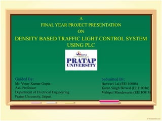
- 1. A FINAL YEAR PROJECT PRESENTATION ON DENSITY BASED TRAFFIC LIGHT CONTROL SYSTEM USING PLC Guided By: Mr. Vinay Kumar Gupta Ass. Professor Department of Electrical Engineering Pratap University, Jaipur. Submitted By: Banwari Lal (EE110006) Karan Singh Berwal (EE110016) Mahipal Mandawaria (EE110018)
- 2. PROJECT OBJECTIVES • Develop a new traffic light control system controlled by programmable logic controller (PLC). • Implement the system on a model of a traffic light.
- 3. PROJECT SCOPE • Construct a model of four way junction of a traffic light model. • Programmed a ladder logic diagram to control the traffic light. • Combine the software part and the hardware part to simulate a traffic light system.
- 4. PROBLEM STATEMENT • The monitoring and control of city traffic light is becoming a major problem in many countries. • The increasing number of vehicles and the lower phase of highways developments have led to traffic congestion problem especially in major cities. • In addition, delays due to traffic congestions also indirectly affect productivity, efficiency, and energy losses.
- 5. AUTOMATION Automation is basically the delegation of human control functions to technical equipment aimed towards achieving: Higher productivity. Superior quality of end product. Efficient usage of energy and raw materials. Improved safety in working conditions etc.
- 6. TYPES OF AUTOMATION Building Automation Example: Lifts, Smoke detectors Office Automation Example: Printers, CCTV cameras Scientific Automation Example: Rocket launching Light Automation Example: Street solar lightening Industrial Automation Example: Automated bottle filling stations , Steel factories etc
- 7. INDUSTRIAL AUTOMATION The use of Computerized or robotic devices to complete manufacturing tasks. PLANT FIELD INSTRUMENT CONTROL SYSTEM HARDWARE CONTROL SOFTWARE CONTROL
- 9. MODE OF OPERATION There are three mode of operation in this traffic light control system. • Density base • Timing mode • Night mode
- 10. COMPONENT OF PROJECT • PLC (Programmable logic controller) • LIMIT SWITCH • INDICATOR • PLYWOOD • OTHER ACCESSORIES
- 11. PLC (Programmable Logic Controller)
- 12. CONTENTS • WHAT IS PLC • WHY PLC? • COMPONENTS OF PLC • PLC OPERATION • PLC PROGRAMMING • APPLICATIONS • ADVANTAGES AND DISADVANTAGES • CONCLUSION
- 13. PLC(PROGRAMMABLE LOGIC CONTROLLER) Programmable Logic Controller (PLC) is an industrial computer that monitors inputs, makes decisions based on its program and controls outputs to automate a process or machine. The automation of many different processes, such as controlling machines or factory assembly lines, is done through the use of small computers called a programmable logic controllers (PLCs).
- 14. WHY PLC? To reduce human efforts . To get maximum efficiency from machine and control them with human logic . To reduce complex circuitry of entire system . To eliminate the high costs associated with inflexible, relay- controlled systems.
- 15. UNDERSTANDING OF PLC (Example ) Machine can be controlled by PLC without human efforts
- 16. MAJOR COMPONENTS OF A PLC PROCESSOR POWER SUPPLY I M N O P D U U T L E O M U O T D P U U L T E PROGRAMMING DEVICE From SENSORS Pushbuttons, contacts, limit switches, etc. To OUTPUT Solenoids, contactors, alarms etc.
- 17. PLC INPUT OUTPUT PUSH BUTTONS 1. INPUT MODULES accepts and converts signals from sensors into a logic signal Ex. : Switches, Pushbuttons. 2. OUTPUT MODULES that convert control instructions a signal that can be used by actuators. Ex. : lamps, alarm. COMPONENTS (INPUT /OUTPUT)
- 18. 3. CENTRAL PROCESSING UNIT(CPU) It is the brain of PLC and governs the activities of the entire PLC systems The CPU consists of following blocks : Arithmetic Logic Unit (ALU), Internal memory of CPU Internal timers ,counters and Flags . The various operations performed are : Scanning I/O bus traffic control, Program execution, Peripheral and External device communication, Data handling and self diagnostics. PROCESSOR 4. MEMORY is the component that stores information, programs and data in a PLC. COMPONENTS (CPU ,MEMORY) Types of memories used in PLCs are read only memory (ROM) and random access memory (RAM).
- 19. 5. POWER SUPPLY Provides the voltage needed to run the primary PLC components. POWER SUPPLY 6. PROGRAMMING DEVICE The programming terminal is used for programming the PLC and monitoring/sequencing PLCs operation. PROGRAMMING DEVICE COMPONENTS (POWER SUPPLY, PROGRAMMING DEVICE)
- 20. CHECK INPUT STATUS First the PLC takes a look at each I/O to determine if it is on or off. EXECUTE PROGRAM Next the PLC executes the program one instruction at a time. UPDATE OUTPUT STATUS Finally the PLC updates the status of the outputs .It updates the outputs based on which inputs were on during the first step. PLC OPERATION
- 21. Ladder logic is a programming language used to develop software for PLC used in industrial control applications. RUNGES RAIL RAIL PLC PROGRAMMING
- 22. ELEMENTS OF LADDER LOGIC NORMALLY OPEN NORMALLY CLOSED (CONTACT) (CONTACT) COILS
- 23. LADDER LOGIC EXAMPLE OR OPERATION A B C In the above diagram, it can be seen that either input A or B is be true (1), or both are true, then the output C is true (1).
- 24. Manufacturing / Machining Food / Beverage Textile Industry Travel Industry Aerospace Printing Industry Traffic light control AREAS OF APPLICATION
- 25. • Replacing Human Operators • Dangerous Environments • Beyond Human Capabilities • Fast • Easily programmed and have an easily understood programming language. • Improves Productivity • Improves Quality ADVANTAGES
- 26. • PLC Devices Are Proprietary • Initial Costs Are High • There's Too Much Work Required In Connecting Wires • Unemployment Rate Increases DISADVANTAGES
- 27. The PLC have in recent years experienced an unprecedented growth as universal element in industrial automation. It can be effectively used in applications ranging from simple control like replacing a small number of relays to complex automation problems. Today the PLCs are used for control & automation job in a single machine & it increases up to full automation of manufacturing / testing process in a factory. CONCLUSION
- 28. LIMIT SWITCH
- 29. CONTENTS • WHAT IS LIMIT SWITCH? • WHY LIMIT SWITCH? • COMPONENTS OF LIMIT SWITCH • LIMIT SWITCH OPERATION • APPLICATIONS • ADVANTAGES AND DISADVANTAGES
- 30. LIMIT SWITCH A limit switch is a switch operated by the motion of a machine part or presence of an object. limit switches are industrial control components manufactured with a variety of operator types, including lever, roller plunger, and whisker type. They can determine the presence or absence, passing, positioning, and end of travel of an object.
- 31. WHY LIMIT SWITCH? Ease of installation Reliability of operation Ruggedness
- 32. COMPONENT OF LIMIT SWITCH NO(Normally Open) NC(Normally Closed) COMMON TERMINAL
- 33. LIMIT SWITCH OPERATION A limit switch is an electromechanical device that consists of an actuator mechanically linked to a set of contacts. When an object comes into contact with the actuator, the device operates the contacts to make or break an electrical connection.
- 34. APPLICATIONS • Controlling temperature • Controlling pressure • Controlling PH level • Counting • Presence or absence of an object • Passing and positioning of an object
- 35. ADVANTAGES Mechanical advantages: • Ease of use. • Simple visible operation. • Durable housing. • Well sealed for reliable operation. • High resistance to different ambient conditions found in industry. • High repeatability. •
- 36. ADVANTAGES Electrical advantages: • Suitable for switching higher power loads than other sensor technologies. • Immunity to electrical noise interference. • Immunity to radio frequency interference (walkie-talkies). • No leakage current. • Minimal voltage drops. • Simple normally open and/or normally closed operation.
- 37. DISADVANTAGES • Shorter contact life than solid-state technology. • Moving mechanical parts wear out eventually. • Not all applications can use contact sensing.
- 38. INDICATOR
- 39. CONTENTS • WHAT IS INDICATOR? • SIGNAL TOPOLOGY • APPLICATIONS • ADVANTAGES AND DISADVANTAGES
- 40. INDIACATOR This project use LED light as an indicator. A PLC for auto change signal after a specific time interval. There are three LED lights are used as indicator. 1. Green 2. Red 3. Yellow
- 41. INDIACATOR Traffic lights, also known as traffic signals, traffic lamps, traffic semaphore, signal lights, stop lights and robots and also known technically as traffic control signals. These are signalling devices positioned at road intersections, pedestrian, crossing and other locations to control competing flows of traffic.
- 42. INDICATOR
- 43. SIGNAL TOPOLOGY • The green light allows traffic to proceed in the direction denoted, if it is safe to do so. • The yellow light provides warning that the signal will be changing from green to red. • A flashing yellow indication is a warning signal. • The red signal prohibits any traffic from proceeding. • A flashing red indication is treated as a stop sign
- 44. APPLICATIONS • Traffic Light. • Rail and Metro. • Industry. • Power outage. • Emergency response.
- 45. ADVANTAGES • Decrease risk. • Save time. • Save money. • Convenient flexibility.
- 46. DISADVANTAGES • Increase in accident. • Delay. • Diverted congestion. • Civil disobedience.
- 47. PLYWOOD
- 48. PLYWOOD A type of strong thin wooden board consisting of two or more layers glued and pressed together with the direction of the grain alternating.
- 49. PLYWOOD • Types of Plywood: softwood plywood hardwood plywood Decorative plywood Flexible plywood
- 50. PLYWOOD • Type – Hardwood plywood • Size – 2 * 2 meter • Thickness – 6 mm • Grade - A
- 51. APPLICATIONS • Panels in concrete form work systems. • Floors, walls and roofs in transport vehicles. • Container floors. • Floors subjected to heavy wear in various buildings and factories. • Scaffolding materials.
- 53. OTHER ACCESSORIES Traffic Pole Divider Paint (Black) Wires Wooden mixture Fevicol Colored paper
- 54. RESULT & CONCLUSSION • The program was burned and then the model was given power supply. • As a result the traffic system operates in a sequential order servicing one lane after the other. • As a result all lanes get service but the lane with higher density gets higher preference.
- 55. REFRENCES • www.atmel.com • www.scribd.com • www.bookrags.com • www.ijater.com • Design of smart traffic controller using embedded system (www.iosrjournals.org) sananas.G.Sayyed, Poonam.V.Pawar, Vishakha.S.Thakare, Snehal.R.Jadhav.