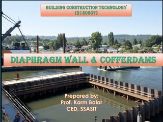
BCT- Module 5 a coffer-dam (Part_2)
•
1 like•616 views

for the subject offered in GTU, BCT module 5 cofferdam & diaphragm wall, for the 3rd sem & also for the 6th sem subject

Recommended
More Related Content
What's hot
What's hot (20)
Similar to BCT- Module 5 a coffer-dam (Part_2)
Similar to BCT- Module 5 a coffer-dam (Part_2) (20)
More from Shree Swami atmanand saraswati inst. of technology, surat
More from Shree Swami atmanand saraswati inst. of technology, surat (20)
Recently uploaded
Recently uploaded (20)
BCT- Module 5 a coffer-dam (Part_2)
- 1. COFFER DAM
- 2. Diaphragm Wall Application Coffer dams Types of Coffer Dams Design features of coffer dams Leakage Prevention Economic Height 2 CONTENTS
- 3. Diaphragm Wall • Diaphragm Walls Are A Method Of Creating A Cast In-situ Reinforced Concrete Retaining Wall Using The Slurry Supported Trench Method. As Such, They Are Often Known As Slurry Walls. However, The Term “Diaphragm Walls” • Standard Width Are 100-200 Mm For Cut Off Wall And 450-1200 Mm For Structural Member. • Diaphragm Walls Provide A Water Tight Barrier And Are Constructed With A Minimum Back Slope Subsidence. • They Are Formed From Reinforced Concrete And Are Constructed As Normal Cast-in-place Walls With Support, Which Become Part Of The Main Structure.
- 4. APPLICATIONS As permanent and temporary foundation walls for deep basements. In earth retention schemes for highway and tunnel projects. As permanent walls for deep shafts for tunnel access. As permanent cut-off walls through the core of earth dams. In congested areas for retention systems and permanent foundation walls. Deep ground water barriers through and under dams.
- 5. Construction Of Diaphragm Wall 5
- 7. Cofferdam for bridge foundations COFFERDAMS
- 8. DEFINITION Cofferdams are temporary enclosures to keep out water and soil so as to permit dewatering and construction of the permanent facility (structure) in the dry. Its temporary structure which is built in a river, lake etc. to remove water from an area and make it possible to carry on the construction work under reasonably dry conditions. Meaning of Coffer Dam : Coffer = Box Cofferdams are usually required for projects such as dams, docks and construction of bridge piers and abutments etc. 8
- 9. 9 watertight. Materials – earth , timber , steel & concrete. Constructed at site of work. Depend- depth , soil condition , difference in water level, availability of materials. total cost of construction, maintenance and pumping is minimum. Stable against bursting, overturning and sliding, under the floods and waves. How it is?
- 10. When it is? To facilitate pile driving operations. To place grillage & raft foundations. To construct foundations of piers & abutments of bridges, dams, docks etc. To provide a working platform for foundations when water is meet with it. To retain Soil & Water. Can be used as either Temporary or Permanent. Main purpose is to provide dry working area for workers. 10
- 11. Civil Engineering: Underground Car Parking, Foundation, Basement Construction Transport Engineering: Bridge Pier, Support Walls, Ramps, Ground Water Retention, Tunnel Work etc. Water Engineering: Weirs, Culverts, Flood Protection Walls, Scour Protection Walls, Securing Embankment etc. Port Construction: Dock Works, Jetty Works etc. 11
- 12. TYPES OF COFFER DAM 1.Earth fill cofferdams - mainly for low level water 2.Rock fill cofferdams 3.Timber Crib or rock filled crib cofferdams - Construction on land and than floated into place, which is also known as Gravity Dam 4.Braced / Sheet Pile Coffer Dam- Consisting of Sheet Piles, mainly used in shallow water depth (i). Single wall coffer dams (ii). Double wall coffer dams (iii). Cellular cofferdams 12
- 13. It is constructed in places where the depth of water is not much, say 1.3 to 1.8 m. The earth bank is carried about one meter above the water level. The top width of the bank should not be less than 1 mtr. and the side slopes in a vary from 1 : 1 to 1 : 2. The earth embankment should be built from a mixture of clay and sand or clay and gravel. In order to prevent the embankment from scouring due to the action of water, side slopes of the bank on water side should be pitched with rubble boulders. EARTH FILL COFFERDAMS
- 14. 1. EARTH FILL COFFERDAMS 14 120to150 cm
- 15. 15
- 16. 16
- 18. 2. ROCK FILL COFFERDAMS 18
- 19. If the depth of water to be retained by the embankment of cofferdam is of order of 3 m . Stone or rubble is used for the embankment. This construction is adopted only if the stone is easily available in the nearby areas. The stones are assembled in the required shape of the embankment and the voids are partially filled with earth and stone-chips. On the waterside, the rock fill is to be provided with an impervious layer of earth. 19
- 20. 20
- 21. 21
- 22. 22
- 23. 23
- 24. 24
- 25. 25
- 26. 26
- 27. 1. SINGLE WALLED COFFER DAM 27 Area to be enclosed is small and the depth of water is more 4.5 to 6 m. Timber piles known as guide piles are first driven deep into the firm ground below the river bed. spacing of the piles may vary between 1.8 to 4.5 m. Longitudinal runners called Wales are then bolted to the guide. 4. SHEET PILE COFFERDAM
- 28. 28 Steel or wooden sheet piles are then driven into the river bed along the Wales and are secured to the Wales by bolts. The sheets on the two faces are braced by trussed arrangement of struts. This helps in increasing the stability of walls against the water pressure. Half-filled bags of sand stacked on the inside and the outside faces of the sheets help in increasing the stability of cofferdam. After the cofferdam is constructed, the water in the enclosed area is pumped out and the construction work is taken up.
- 29. 29
- 30. 30
- 31. 31
- 32. 32
- 33. DOUBLE WALLED COFFERDAMS Double-walled cofferdam is provided to enclose a larger area. Its construction is essentially the same as that of a single-walled cofferdam except that in place of one wall, a pair of walls with a gap in between is used all along the boundary of the space to be enclosed. This type of cofferdam can be used in depth of water up to 12 m. - The double wall cofferdams are of two types: (I) Ohio – river type cofferdams (ii) Timber or steel sheeting cofferdams
- 35. 35
- 36. 36
- 37. Timber Sheet Pile Timber sheet pile were extensively used for cofferdam when depth of water is about 6 to 10 m. It can be gradually replaced with steel pile. It can only be used for small depth since no deep piling in 37
- 38. Timber or steel sheeting cofferdams
- 41. 41
- 42. TIMBER CRIB OR ROCK FILLED CRIB COFFERDAMS Constructed on land and floated into place It consists of a unit or a cell open at the bottom and having the framework of horizontal timber members. Hollow space formed are then filled with rock or gravel Depth of water – 10 to 20 m Used for wide excavation and rocky river bottoms 42
- 43. 3. TIMBER CRIB OR ROCK FILLED CRIB COFFERDAMS 43
- 44. 44 OHIO RIVER TYPE COFFERDAM Ohio river in USA. Used in hard & soft bed (no erosion). Unsuitable in deep water & swift flow. Construction Wales fixed at 1.50m vertically. Wale joints, double vertical planks are provided. Tie rods threaded & cross braces fixed. Fixes sheet piles. Beams (inside & outside) Removing safely.
- 45. 45
- 46. 46
- 47. 47
- 49. 49
- 50. 50
- 51. 51
- 52. 52
- 54. CELLULAR COFFERDAMS - The cellular cofferdams are mostly used for dewatering large areas , where the depth of water may be 19 to 21 m. - Mostly used the construction of marine structures like Dams, Locks etc. - The two common shapes of the cellular cofferdam are: (i) Circular type (ii) Diaphragm type 54
- 55. Circular type cellular cofferdam: The circular type of cellular cofferdam has the advantage that each cell may be filled completely to the top before starting the construction of the next cell without causing any distortion to the shell of the cofferdam. Thus, when one cell is completely filled up with crushed stone, broken bricks, gravel and sand. It can be used for placing crane or other equipment required for the construction of other cells.
- 56. 56 In addition, each cell acts as a self-supporting independent unit and in case one of the cells collapses due to scour or interlock damage or some other reason, it does not produce any adverse effect on the neighboring cells. It is found that the interlock stresses reach their maximum permissible value when the diameter of cell is about 21 meter. Hence in case, from design consideration it is necessary to have effective width of the cofferdam more than 21 meter, diaphragm type of cofferdam must be used.
- 57. 57
- 58. 58
- 59. 59
- 60. 60
- 61. 61
- 62. 62
- 63. 63
- 64. Diaphragm type cellular cofferdam: • This Consists of a series of arcs of steel sheet piles connected as shown in the image. • The straight diaphragm wails are connected to each other by steel piles arranged in the form of arches on either sides. • The radius of the connecting arcs is generally made equal to the distance between the straight diaphragm walls. 64
- 65. 65 • After the cells are driven to the required depth, they are filled with earth, sand, gravel or other filling material. In this type of cofferdam, as the diaphragm which separates the two cells is a straight wall, it is necessary to fill adjacent cells at approximately the same rate. • If this is not done, the unbalanced pressure from the fill will distort the diaphragm (cross-walls) which may result in the failure of the interlocks. • In this respect, the circular type cofferdam has the advantage over the diaphragm type cofferdam because in the former, it is not necessary to fill the adjacent cells at the same time.
- 66. 66
- 67. 67
- 68. 68 These are actually small concrete dams and they have been used economically on many jobs. The framework usually consist of pre cast R.C.C piles and sheets. The pre cast R.C.C sheet piles are provided with suitable edges and they are driven in a similar manner to steel sheet piles. The main disadvantage of this cofferdam is that it is costly. But when it is to be incorporated as a part of permanent structure it proves to be economical. CONCRETE COFFERDAM
- 69. 69
- 70. MOVABLE OR SUSPENDED COFFERDAMS Where there are numbers of repetition work in under water foundations ,such as in the piers of multi span river bridges , it is economical to design the cofferdams to be moved as a single unit from one foundation to another. 70
- 71. 71
- 72. 72 Water may leak through the underground flow of water or through the piling sheet of the cofferdam. The following measures can be adopted to prevent leakages in cofferdam. 1.Water entering the dewatered area through fissures or cracks in the rocks can be stopped by grouting the fissures by cement grout. 2. Clay or mixture of clay and sand can be dumped in form of beams both on inside and outside faces of the cofferdam. 3. Cracks or fine joints or nail holes in the sheet piles should be closed using bitumen or cement mortar. LEAKAGE PREVENTION IN COFFERDAMS
- 73. 73 4. If a lot of leakages is taking place and no measures stated above have been to control it, the water face of the cofferdam may be completely covered with canvass coated with tar or tarpaulin. 5. In case of double-walled cofferdams leakage is generally because of insufficient compaction of the filling material. In this case, measures to control seepage through filling material should be adopted. 6. Sufficient grease applied at interlocks of sheet piles also helps check leakage of water.
- 74. DESIGN FEATURES OF COFFERDAMS The design of a cofferdam depends on various factors such as. (i) Hydrostatic head of Water (ii) Dimensions of the area to be covered by the cofferdams (iii) Subsoil conditions (iv) Fluctuations of outside water level (v) Possibility of erosion (vi) Presence of ice 74
- 75. A purely theoretically designed cofferdam may fail for factors unaccounted in its design. Therefore ,become necessary to combine practical knowledge or experience with the theoretical aspects in the design of a cofferdam. For width and Depth of cofferdam : for H < 3 m, W = H H > 3 m, W = 3 + 1/3*(H - 3) Where, W = Width of cofferdam in metres H = Height of water above river bed in metres 75
- 76. Economic Height of Coffer Dam 1.Depth of Water Low depth => Earthen Dam High Depth => Sheet Pile Coffer Dam 2.Current and nature of flowering of Sheet Pile High Current => Sheet Pile Coffer Dam (Higher Seepage Control Capacity) Low Current => Earthen or any other Dam (Less Seepage Control Capacity) 76 The maximum height of cofferdam for which its total cost is minimums known as the most economic height of cofferdam.
- 77. 3.Type and Period of Work Short Duration Work => Timber Dam Long Duration work => Sheet Pile Coffer Dam 4.High and Low Tide Level of Reservoir Sheet Pile must have top level slightly higher than that of the HTL. So that even in extreme case water can not over top the coffer dam, to achieve the dry working through out the season. 77
- 78. 78 Extra chees & knowledge good for body…
- 82. JOINTS IN SHEET PILING
- 84. CASE STYUDY
- 85. Burj AlArab Cofferdam &Rigging FirasAl Shalabi & SunnyMahajan CE505 ProjectPresentation 1
- 86. Background Dubai, UAE The first 7 stars hotel in theworld The start of Dubai’s new vision of attracting new investments in areas outside the oilindustry. If you want to book a night there it will cost you around $2000 321 meters height from thesea. 8 6
- 87. Theconstruction Two main phases: The manmade Island (ourfocus) The building 8 7
- 88. Building theisland Temporary tube piles driven into sea bed Temporary sheet piles and tierods driven into sea bed to support boundary rocks Sheet pilewall 8 8 Tubularpile
- 89. Rock armor 8 9 Permanentboundary rock bunds (rock armor) depositedon both sides of the sheet piles No solid ground under the building just weak sand (up to 180 meters deep with no solid ground). So it was decidedto go withfriction piles. Sand fill Building theisland
- 90. PermanentSHED units placed around the island to dissipate the action of waves and protectit. 2M (6.5ft) diameter 43M (141ft) deep piles weredriven throughthe island and seabed Main buildingpiles 6 SHED units
- 91. 91
- 92. 92
- 93. 93
- 94. Excavationsbegan in theislandto removethehydraulicfill Acoffer dam was being built while excavating 2M (6.5 ft) thick concreteplug slab laid on the base of the island to prevent the base from popping out because of the seapressure Reinforced concreteretaining wallbuilt Theconstruction of thebasement started 94 Concreteslab
- 95. Completed Island Completed in threeyears 95
- 96. GAMMON INDIA LIMITED CABLE -STAY BRIDGE SURAT (EXCAVATION WORK) 96
- 97. Bracing welding work in progress 97
- 98. 98
- 99. 99
- 100. 10 0
- 101. SHEET PILE COFFER DAM 10 1
- 102. 10 2
- 103. 103
- 104. 104
- 105. PHOTO GALLERY OF COFFER DAM 105
- 106. 10 6
- 107. 10 7
- 118. 11 8
- 121. 12 1
- 122. 122