SlideShare ist ein Scribd-Unternehmen logo
1 von 83
Downloaden Sie, um offline zu lesen
TYPES OF FRACTURE
Brittle vs. Ductile Fracture
• Ductile materials - extensive plastic deformation and energy
absorption (“toughness”) before fracture
• Brittle materials - little plastic deformation and low energy
absorption before fracture.
Fracture: Refers to the failure of a material under load by
breaking into two or more pieces. Fracture can occur under
all service conditions.
➢ Materials subjected to alternating or cyclic loading (as in
machines) fail due to fatigue(fatigue fracture)
➢ Materials used at high temperatures can fail due to creep
fracture
3
Fracture mechanisms
• Ductile fracture
– Occurs with plastic deformation
• Brittle fracture
– Little or no plastic deformation
– Catastrophic
Ductile Brittle
Ductile, Creep
Brittle
Cracks choose the path of least resistance
Brittle fractures display either transgranular or intergranular fracture
A. Very ductile, soft metals (e.g. Pb(lead), Au(Aurum-Gold) at room
temperature, other metals, polymers, glasses at high temperature.
B. Moderately ductile fracture, typical for ductile metals
C. Brittle fracture, cold metals, ceramics, ice
(a) Necking (b) Formation of microvoids (c) Coalescence of microvoids
to form a crack (d) Crack propagation by shear deformation
(e) Fracture
➢ Ductile fracture is the rupture of a material after a considerable amount
of plastic deformation.
➢ Material begin to neck beyond the ultimate tensile strength
➢ The neck refers to the reduced cross-section of the specimen near the
middle.
➢ Cracks are found to nucleate at brittle particles, either the natural kind
found in multiphase materials, e.g., cementite in steel, or foreign
inclusions, e.g., oxide inclusions in copper.
➢ When a brittle particle is present, it is difficult to maintain compatibility
in the neck region between the continuously deforming matrix and the
nondeforming particle. This results in the formation of very tiny voids
near the matrix-particle interface.
➢ If fracture initiates at pores in the neck region, then the voids are
already present. The voids grow with increasing deformation and
ultimately reach sizes of the order of a mm. At this stage, the material
may tear apart.
➢ This model of ductile fracture is supported by the finding that materials
of ultra high purity, which do not have inclusions or pores, do rupture
in a fully ductile manner, that is after thinning down to a point or an
edge.
The basic steps are: void formation, void coalescence (also known as crack
formation), crack propagation, and failure, often resulting in a cup-and-cone
shaped failure surface.
• Evolution to failure:
• Resulting
fracture
surfaces
(steel)
particles
serve as void
nucleation
sites.
Fracture surface of tire cord wire
loaded in tension.
Moderately Ductile Failure
necking
s
void
nucleation
void growth
and linkage
shearing
at surface
fracture
Rough surface
In ductile fracture, extensive plastic deformation takes place before fracture.
The terms rupture or ductile rupture describe the ultimate failure of tough
ductile materials loaded in tension. Rather than cracking, the material "pulls
apart," generally leaving a rough surface. In this case there is slow
propagation and an absorption of a large amount energy before fracture.
Many ductile metals, especially materials with high purity, can sustain very
large deformation of 50–100% or more strain before fracture under favorable
loading condition and environmental condition. The strain at which the
fracture happens is controlled by the purity of the materials.
At room temperature, pure iron can undergo deformation up to 100% strain
before breaking, while cast iron or high-carbon steels can barely sustain 3%
of strain.
Because ductile rupture involves a high degree of plastic deformation, the
fracture behavior of a propagating crack as modeled above changes
fundamentally. Some of the energy from stress concentrations at the crack
tips is dissipated by plastic deformation before the crack actually propagates.
Brittle fracture in CI
Ductile vs Brittle Failure
Very
Ductile
Moderately
Ductile
Brittle
Fracture
behavior:
Large Moderate Small
• Ductile
fracture is usually
desirable!
Ductile:
warning before
fracture
Brittle:
No
warning
23
• Ductile failure:
--one piece
--large deformation
Example: Failure of a Pipe
• Brittle failure:
--many pieces
--small deformation
Ductile vs. Brittle Failure
cup-and-cone fracture brittle fracture
Since brittle fracture is most unpredictable, usually a notch will be
introduced to simulate the conditions.
Notch-impact testing
26
Impact Testing
final height initial height
(Charpy)
Two standard tests, the Charpy and Izod, measure the impact energy
(the energy required to fracture a test piece under an impact load),
also called the notch toughness.
DBTT
Fracture toughness is a property which describes the ability of a material containing a
crack to resist fracture, and is one of the most important properties of any material for
many design applications.
Fracture toughness is a quantitative way of expressing a material's resistance
to brittle fracture when a crack is present. If a material has much fracture toughness it will
probably undergo ductile fracture. Brittle fracture is very characteristic of materials with less
fracture toughness.
An impact toughness versus temperature graph for a
steel is shown in the image. It can be seen that at
low temperatures the material is more brittle and
impact toughness is low.
At high temperatures the material is more ductile
and impact toughness is higher.
The transition temperature is the boundary between
brittle and ductile behavior and this temperature is
often an extremely important consideration in the
selection of a material.
Greater the impact energy, the more ductile the material.
copper remains ductile at all temperatures in the range covered by this experiment
FCC metals remain ductile down to very low temperatures (Cu, Ni)
➢It can be seen that copper remains ductile at all temperatures in the range covered by
this experiment.
➢Nylon can be seen to be going through its glass transition at above 50 °C, and hence
shows a brittle to ductile transition.
➢In contrast, acrylic remains brittle, as seen from the consistently low impact energies.
➢Zinc becomes more ductile at temperatures above room temperature.
➢Mild steel shows a ductile-brittle transition at around -60 °C.
➢Results for aluminium show that it become slightly less ductile as the temperature is
increased, and all the values for impact energy lie between the ductility of copper and
the brittleness of acrylic. Flow is always easier than cleavage in aluminium so there is
never a ductile-brittle transition observed. The decrease of overall ductility with
temperature seen in aluminium arises from dynamic recovery.
33
• Pre-WWII: The Titanic • WWII: Liberty ships
• Problem: Used a type of steel with a DBTT ~ Room temp.
Design Strategy:
Stay Above The DBTT!
34
Engineering Fracture Design
• Avoid sharp corners!
s
r ,
fillet
radius
w
h
o
smax
Ship-cyclic loading from waves.
FATIGUE
Computer chip-cyclic
thermal loading.
Hip implant-cyclic
loading from walking.
Fatigue Failure
Fatigue is the weakening of a material caused by repeatedly applied loads. It is
the progressive and localized structural damage that occurs when a material is
subjected to cyclic loading. The nominal maximum stress values that cause such
damage may be much less than the strength of the material typically quoted as
the ultimate tensile stress limit, or the yield stress limit.
Fatigue occurs when a material is subjected to repeated loading and unloading.
Crankshaft after fatigue failure
Aircraft Landing Gear
Fatigue
Fatigue is caused by repeated application of stress to the metal.
It is the failure of a material by fracture when subjected to a cyclic
stress.
Fatigue is distinguished by three main features.
i) Loss of strength
ii) Loss of ductility
iii) Increased uncertainty in strength and service life
This type of failure occurs in Metals and Polymers, While Ceramics do not undergo
this type of failure!!
Fatigue is an important form of behavior in all materials including
metals, plastics, rubber and concrete.
All rotating machine parts are subjected to alternating stresses.
Example: aircraft wings are subjected to repeated loads, oil and gas
pipes are often subjected to static loads but the dynamic effect of
temperature variation will cause fatigue.
Because of the difficulty of recognizing fatigue conditions, fatigue
failure comprises a large percentage of the failures occurring in
engineering.
To avoid: stress concentrations, rough surfaces and tensile residual
stresses, fatigue specimens must be carefully prepared.
Fatigue – Stress patterns
• Three different fluctuating stress-
time modes are possible:
(i) Reversed stress cycle,
(ii) Repeated stress cycle,
(iii) Random stress cycle.(Irregular
stress)
Stress cycles that can cause fatigue failure are characterized by following parameters:
Mean Stress affects Fatigue Life
Note, Mean σm = 0, for
Reverse stress cycling.
Mean σm = +ve
quantity for Repeat
stress cycling
Mean (σm) has an
effect on fatigue life.
Increasing the mean
stress level leads to a
decrease in fatigue life.
Crack Initiation and Propagation
The process of fatigue failure is characterized by three distinct steps:
(1) Crack initiation:
Cracks always nucleate on the surface of a component at some point
of stress concentration.
Crack nucleation sites:
surface scratches,
sharp fillets,
keyways,
threads,
dents, and the like…
(2) Crack Propagation:
Crack advances incrementally (during this step) with each stress cycle
(3) Failure:
Failure occurs very rapidly once the advancing crack has reached a
critical size.
Fatigue Testing – The S-N Curve
• Fatigue testing is carried out using standard machines, to
simulate the real service conditions:
(i) Stress level,
(ii) Time-frequency,
(iii) Stress pattern.
Rotating Beam test
specimen, post test with crack
Specimen: ASTM E466 standards
Reverse bending type fatigue testing machine
Stress (MPa)
No.of cycles to
failure
30 9500000
60 4000000
90 2000000
120 850000
140 600000
30 9400000
60 4000000
90 2100000
120 840000
140 595000
Fatigue Testing – The S-N
Curve
• Fatigue Limit (Endurance Limit):
For some steels and Ti alloys,
the S-N curve becomes
horizontal at higher ‘N’ values
for a limiting stress, below
which fatigue failure does not
occur. For steels, fatigue limit
range between 35% and 60% of
the tensile strength.
• Fatigue strength: Non-ferrous
alloys (Al, Cu, Mg) do not have
Fatigue Limit. Fatigue strength is
defined as the stress level at
which failure will occur for
some specified number of
cycles (e.g, 107 cycles).
Fatigue Testing – The S-N
Curve
• Fatigue Life: Number of
cycles to cause failure at a
specified stress level, as
taken from the S-N plot.
The S-N Curve
A very useful way to visual the failure for a specific material is with the S-N
curve.
The “S-N” means stress verse cycles to failure, which when plotted using
the stress amplitude on the vertical axis and the number of cycle to failure
on the horizontal axis.
An important characteristic to this plot as seen is the “fatigue limit”.
➢ The point at which the curve flatters out is termed as fatigue limit and is
well below the normal yield stress.
➢ The significance of the fatigue limit is that if the material is loaded below
this stress, then it will not fail, regardless of the number of times it is
loaded.
➢ Materials such as aluminium, copper and magnesium do not show a
fatigue limit; therefore they will fail at any stress and number of cycles.
➢ Other important terms are fatigue strength and fatigue life.
➢ The fatigue strength can be defined as the stress that produces failure in a
given number of cycles usually 107.
➢ The fatigue life can be defined as the number of cycles required for a
material to fail at a certain stress.
Fracture surface of a
rotating steel shaft that
experienced fatigue
failure of metals.
Benchmark ridges are
visible to the unaided
eye as shown in the
photograph.
Striations: Each bench
mark will contain many
striations which can be
seen using SEM.
Crack Initiation and Propagation
TEM showing
fatigue
STRIATIONS in
Al.
Note presence
of striations and
benchmark
ridges confirm
that the failure
is fatigue.
Fatigue failure of metal
surface.
A crack formed at the top
edge.
The smooth region also
near the top corresponds
to the area over which
the crack propagated
slowly.
Dull and fibrous fracture
surface reveals fracture
was rapid.
Failure can be recognized by the appearance of fracture.
For a typical fracture ,Two distinct zones can be distinguished – a smooth
zone near the fatigue crack itself which, has been smoothened by the
continual rubbing together of the cracked surfaces, and a rough crystalline-
looking zone which is the final fracture.
Occasionally fatigue cracks show rough concentric rings which correspond to
successive positions of the crack.
Fatigue life improves by incorporating rounded fillet into a rotating
shaft at the point where there is a change in diameter.
(a) No fillet; bad design. (b) Fillet provided; good design.
Factors affecting fatigue properties
Surface finish:
Scratches dents identification marks can act as stress raisers and so reduce
the fatigue properties.
Electro-plating produces tensile residual stresses and have a detrimental
effect on the fatigue properties.
Temperature:
As a consequence of oxidation or corrosion of the metal surface increasing,
increase in temperature can lead to a reduction in fatigue properties.
Residual stresses:
Residual stresses are produced by fabrication and finishing processes.
Residual stresses on the surface of the material will improve the fatigue
properties.
Heat treatment:
Hardening and heat treatments reduce the surface compressive stresses;
as a result the fatigue properties of the materials are getting affected.
Stress concentrations:
These are caused by sudden changes in cross section holes or sharp
corners can more easily lead to fatigue failure. Even a small hole lowers
fatigue-limit by 30%.
Factors affecting fatigue properties
Fatigue fracture results from the presence of fatigue cracks, usually initiated
by cyclic stresses, at surface imperfections such as machine marking and slip
steps.
The initial stress concentration associated with these cracks are too low to
cause brittle fracture they may be sufficient to cause slow growth of the
cracks into the interior.
Eventually the cracks may become sufficiently deep so that the stress
concentration exceeds the fracture strength and sudden failure occurs.
The extent of the crack propagation process depends upon the brittleness of
the material under test.
In brittle materials the crack grows to a critical size from which it propagates
right through the structures in a fast manner, whereas with ductile materials
the crack keeps growing until the remaining area cannot support the load
and an almost ductile fracture suddenly occurs.
Fatigue Failure
To secure satisfactory fatigue life
▪ Modification of the design to avoid stress concentration eliminating sharp
recesses and severe stress raisers.
▪ Precise control of the surface finish by avoiding damage to surface by
rough machining, punching, stamping, shearing etc.
▪ Control of corrosion and erosion or chemical attack in service and to
prevent of surface decarburization during processing of heat treatment.
▪ Surface treatment of the metal.
The endurance limit for the material will be approximately 45 to
50% of the UTS if the surface of the test specimen is smooth and
polished.
1. Small scratches, tool
marks on surface will
limit the fatigue life.
2. Improving the surface-
finish by polishing will
enhance fatigue life.
3. Residual compressive
stresses are introduced
into ductile metals
mechanically by
localized plastic
deformation, with in
the outer surface region
by Shot peening.
Shot Peening
Case hardening improves fatigue life
Case hardening with
carbon or nitrogen
increases the hardness
of the surface for steels.
The increased hardness
of the case improves
the wear resistance and
fatigue life.
PHYSICAL METALLURGY AND MATERIALS ENGINEERING
Hall-Petch equation:
Yield stress is inversely
proportional to the
square root of grain
diameter (grain size).
Where,
σy, is yield stress;
σ0 and ky are material
dependent constants;
d, is grain diameter
(grain size).
𝝈 𝒚 = 𝝈 𝟎 +
𝒌 𝒚
𝒅
Equicohesive Temperature
1. Strength of the GB = Strength of Grain at the ECT
2. Below ECT fine grain sized material is stronger due to large number of
grain boundaries are present.
3. Above ECT large grain sized material is stronger due to less tendency for
grain boundary sliding.
FAILURE DUE TO TORSION
Until the advent of variable speed drives (VSDs), torsional fatigue
failures were rare: Equipment designers could anticipate operating
speeds and excitation frequencies and engi-neer around them.
The purpose of a VSD is to allow operation at a wide range of
speeds. That, unfortunately, has led to many motor and driven-shaft
failures due to torsional-fatigue factors.
While the most common torsional fatigue cracks start at the sharp
corner (stress concentration) at the bottom of the keyway when
couplings are poorly fitted, another common appearance is the
diagonal shaft crack
PREVENTING TORSIONAL FATIGUE FAILURES
Torsional fatigue failure prevention:
Correct machining, assembly and installation to eliminate:
➢Incorrect fit/finish of a shaft and bore.
➢Small radius in a keyseat.
➢Excess clearance between the key and keyseat.
➢Misalignment.
These are the easiest to fix. Frequently, the effort stops here and the failures continue.
However, with more investigation, torsional fatigue failures can be eliminated.

Weitere ähnliche Inhalte

Was ist angesagt?

Fatigue of materials
Fatigue of materialsFatigue of materials
Fatigue of materialsBilal
 
Slip and twiniing
Slip and twiniingSlip and twiniing
Slip and twiniingGopinath Guru
 
Sheet metal-forming-processes
Sheet metal-forming-processesSheet metal-forming-processes
Sheet metal-forming-processessahilslideshare
 
Heat treatment Process
Heat treatment ProcessHeat treatment Process
Heat treatment ProcessKeval Patil
 
Pattern allowances in metal casting
Pattern allowances in metal castingPattern allowances in metal casting
Pattern allowances in metal castingAndrĂŠs EscĂĄrraga
 
Metal forming processes full
Metal forming processes fullMetal forming processes full
Metal forming processes fullNaman Dave
 
Fatigue and creep
Fatigue and creepFatigue and creep
Fatigue and creepMathews Naveen
 
Superalloys
SuperalloysSuperalloys
SuperalloysN.Prakasan
 
Super plastic forming and explosive forming
Super plastic forming and explosive formingSuper plastic forming and explosive forming
Super plastic forming and explosive formingGovt islamia college kasur
 
Cold isostatic pressing
Cold isostatic pressingCold isostatic pressing
Cold isostatic pressingLahiru Dilshan
 
05 dislocation theory
05 dislocation theory05 dislocation theory
05 dislocation theoryMuhammad Feroze
 
Jominy end quench hardenability test
Jominy end quench hardenability testJominy end quench hardenability test
Jominy end quench hardenability testTejas Atyam
 
Surface hardening
Surface hardeningSurface hardening
Surface hardeningSumanGhosh141
 
Hsla steels
Hsla steelsHsla steels
Hsla steelsN.Prakasan
 

Was ist angesagt? (20)

Fatigue of materials
Fatigue of materialsFatigue of materials
Fatigue of materials
 
Slip and twiniing
Slip and twiniingSlip and twiniing
Slip and twiniing
 
Sheet metal-forming-processes
Sheet metal-forming-processesSheet metal-forming-processes
Sheet metal-forming-processes
 
Heat treatment Process
Heat treatment ProcessHeat treatment Process
Heat treatment Process
 
Pattern allowances in metal casting
Pattern allowances in metal castingPattern allowances in metal casting
Pattern allowances in metal casting
 
Metal forming processes full
Metal forming processes fullMetal forming processes full
Metal forming processes full
 
5.moulding sand
5.moulding sand5.moulding sand
5.moulding sand
 
Fatigue and creep
Fatigue and creepFatigue and creep
Fatigue and creep
 
Superalloys
SuperalloysSuperalloys
Superalloys
 
Fracture Mechanics & Failure Analysis Lecture 1
Fracture Mechanics & Failure Analysis Lecture 1Fracture Mechanics & Failure Analysis Lecture 1
Fracture Mechanics & Failure Analysis Lecture 1
 
Super plastic forming and explosive forming
Super plastic forming and explosive formingSuper plastic forming and explosive forming
Super plastic forming and explosive forming
 
Cold isostatic pressing
Cold isostatic pressingCold isostatic pressing
Cold isostatic pressing
 
05 dislocation theory
05 dislocation theory05 dislocation theory
05 dislocation theory
 
Jominy end quench hardenability test
Jominy end quench hardenability testJominy end quench hardenability test
Jominy end quench hardenability test
 
Shell molding process
Shell molding processShell molding process
Shell molding process
 
Extrusion defects
Extrusion defectsExtrusion defects
Extrusion defects
 
Forging
ForgingForging
Forging
 
Surface hardening
Surface hardeningSurface hardening
Surface hardening
 
Hsla steels
Hsla steelsHsla steels
Hsla steels
 
Steel Making: Ingot casting
Steel Making: Ingot casting Steel Making: Ingot casting
Steel Making: Ingot casting
 

Ähnlich wie TYPES OF FRACTURE MECHANISMS

DJJ3213 MATERIAL SCIENCE CHAPTER 3 NOTE.ppt
DJJ3213 MATERIAL SCIENCE CHAPTER 3 NOTE.pptDJJ3213 MATERIAL SCIENCE CHAPTER 3 NOTE.ppt
DJJ3213 MATERIAL SCIENCE CHAPTER 3 NOTE.pptfieyzaadn
 
Component failure in road traffic accident by ayoub el amri
Component failure in road traffic accident by ayoub el amriComponent failure in road traffic accident by ayoub el amri
Component failure in road traffic accident by ayoub el amriAyoub Elamri
 
Failure Analysis.pptx
Failure Analysis.pptxFailure Analysis.pptx
Failure Analysis.pptxAlejandroOlaya10
 
Chemical Engineering Materials-- Failure of Metals : Fracture , Fatigue & Creep
Chemical Engineering Materials-- Failure of Metals : Fracture , Fatigue & CreepChemical Engineering Materials-- Failure of Metals : Fracture , Fatigue & Creep
Chemical Engineering Materials-- Failure of Metals : Fracture , Fatigue & CreepAjinkya Khandizod
 
Fracture mechanics
Fracture mechanicsFracture mechanics
Fracture mechanicsmanojg1990
 
Zeus impactand plastics
Zeus impactand plasticsZeus impactand plastics
Zeus impactand plasticsclose2u23
 
Seminar on fatigue
Seminar on fatigueSeminar on fatigue
Seminar on fatigueTushar Aneyrao
 
super plastic forming- rubber pad forming
super plastic forming- rubber pad formingsuper plastic forming- rubber pad forming
super plastic forming- rubber pad formingPravinkumar
 
Ch9 failure mechanisms
Ch9 failure mechanismsCh9 failure mechanisms
Ch9 failure mechanismsdhyun
 
Damage tolerance and fracture mechanics
Damage tolerance and fracture mechanicsDamage tolerance and fracture mechanics
Damage tolerance and fracture mechanicsDixi Patel
 
Lecture 04
Lecture 04Lecture 04
Lecture 04luyenkimnet
 
Chapter 8. Mechanical Failure - Failure mechanisms
Chapter 8. Mechanical Failure - Failure mechanismsChapter 8. Mechanical Failure - Failure mechanisms
Chapter 8. Mechanical Failure - Failure mechanismsNamHuuTran
 
mechanical failure.pptx
mechanical failure.pptxmechanical failure.pptx
mechanical failure.pptxWallBert1
 
mechanical failure.pptx
mechanical failure.pptxmechanical failure.pptx
mechanical failure.pptxAbhijeetSingh652
 
METALS_GROUP4.pptx
METALS_GROUP4.pptxMETALS_GROUP4.pptx
METALS_GROUP4.pptxDharenOla3
 
FRICTION.pptx
FRICTION.pptxFRICTION.pptx
FRICTION.pptxManjunathtv2
 
Simulation of Critical Crack Length Propagation Using Fracture Mechanics
Simulation of Critical Crack Length Propagation Using Fracture MechanicsSimulation of Critical Crack Length Propagation Using Fracture Mechanics
Simulation of Critical Crack Length Propagation Using Fracture Mechanicsijceronline
 

Ähnlich wie TYPES OF FRACTURE MECHANISMS (20)

DJJ3213 MATERIAL SCIENCE CHAPTER 3 NOTE.ppt
DJJ3213 MATERIAL SCIENCE CHAPTER 3 NOTE.pptDJJ3213 MATERIAL SCIENCE CHAPTER 3 NOTE.ppt
DJJ3213 MATERIAL SCIENCE CHAPTER 3 NOTE.ppt
 
Component failure in road traffic accident by ayoub el amri
Component failure in road traffic accident by ayoub el amriComponent failure in road traffic accident by ayoub el amri
Component failure in road traffic accident by ayoub el amri
 
Failure Analysis.pptx
Failure Analysis.pptxFailure Analysis.pptx
Failure Analysis.pptx
 
Chemical Engineering Materials-- Failure of Metals : Fracture , Fatigue & Creep
Chemical Engineering Materials-- Failure of Metals : Fracture , Fatigue & CreepChemical Engineering Materials-- Failure of Metals : Fracture , Fatigue & Creep
Chemical Engineering Materials-- Failure of Metals : Fracture , Fatigue & Creep
 
Fracture mechanics
Fracture mechanicsFracture mechanics
Fracture mechanics
 
Zeus impactand plastics
Zeus impactand plasticsZeus impactand plastics
Zeus impactand plastics
 
Seminar on fatigue
Seminar on fatigueSeminar on fatigue
Seminar on fatigue
 
super plastic forming- rubber pad forming
super plastic forming- rubber pad formingsuper plastic forming- rubber pad forming
super plastic forming- rubber pad forming
 
Ch9 failure mechanisms
Ch9 failure mechanismsCh9 failure mechanisms
Ch9 failure mechanisms
 
Damage tolerance and fracture mechanics
Damage tolerance and fracture mechanicsDamage tolerance and fracture mechanics
Damage tolerance and fracture mechanics
 
Fracture
FractureFracture
Fracture
 
Lecture_03.ppt
Lecture_03.pptLecture_03.ppt
Lecture_03.ppt
 
Lecture 04
Lecture 04Lecture 04
Lecture 04
 
Chapter 8. Mechanical Failure - Failure mechanisms
Chapter 8. Mechanical Failure - Failure mechanismsChapter 8. Mechanical Failure - Failure mechanisms
Chapter 8. Mechanical Failure - Failure mechanisms
 
mechanical failure.pptx
mechanical failure.pptxmechanical failure.pptx
mechanical failure.pptx
 
mechanical failure.pptx
mechanical failure.pptxmechanical failure.pptx
mechanical failure.pptx
 
METALS_GROUP4.pptx
METALS_GROUP4.pptxMETALS_GROUP4.pptx
METALS_GROUP4.pptx
 
FRICTION.pptx
FRICTION.pptxFRICTION.pptx
FRICTION.pptx
 
Simulation of Critical Crack Length Propagation Using Fracture Mechanics
Simulation of Critical Crack Length Propagation Using Fracture MechanicsSimulation of Critical Crack Length Propagation Using Fracture Mechanics
Simulation of Critical Crack Length Propagation Using Fracture Mechanics
 
Impact test
Impact testImpact test
Impact test
 

Mehr von Kunduru Srinivasulu Reddy

K.Srinivasulureddy-SNIST-Metallurgy & Material Science-MMS-UNIT-1
K.Srinivasulureddy-SNIST-Metallurgy & Material Science-MMS-UNIT-1K.Srinivasulureddy-SNIST-Metallurgy & Material Science-MMS-UNIT-1
K.Srinivasulureddy-SNIST-Metallurgy & Material Science-MMS-UNIT-1Kunduru Srinivasulu Reddy
 
Unit 1-k.srinivasulureddy-Metallurgy & Material science
Unit 1-k.srinivasulureddy-Metallurgy & Material scienceUnit 1-k.srinivasulureddy-Metallurgy & Material science
Unit 1-k.srinivasulureddy-Metallurgy & Material scienceKunduru Srinivasulu Reddy
 
Unit 3-k.srinivasulureddy-MMS-metallurgy & material science-snist
Unit 3-k.srinivasulureddy-MMS-metallurgy & material science-snistUnit 3-k.srinivasulureddy-MMS-metallurgy & material science-snist
Unit 3-k.srinivasulureddy-MMS-metallurgy & material science-snistKunduru Srinivasulu Reddy
 

Mehr von Kunduru Srinivasulu Reddy (6)

K.Srinivasulureddy-SNIST-Metallurgy & Material Science-MMS-UNIT-1
K.Srinivasulureddy-SNIST-Metallurgy & Material Science-MMS-UNIT-1K.Srinivasulureddy-SNIST-Metallurgy & Material Science-MMS-UNIT-1
K.Srinivasulureddy-SNIST-Metallurgy & Material Science-MMS-UNIT-1
 
Unit 1-k.srinivasulureddy-Metallurgy & Material science
Unit 1-k.srinivasulureddy-Metallurgy & Material scienceUnit 1-k.srinivasulureddy-Metallurgy & Material science
Unit 1-k.srinivasulureddy-Metallurgy & Material science
 
Unit 3-k.srinivasulureddy-MMS-metallurgy & material science-snist
Unit 3-k.srinivasulureddy-MMS-metallurgy & material science-snistUnit 3-k.srinivasulureddy-MMS-metallurgy & material science-snist
Unit 3-k.srinivasulureddy-MMS-metallurgy & material science-snist
 
Theory of Metal Cutting
Theory of Metal CuttingTheory of Metal Cutting
Theory of Metal Cutting
 
Engineering drawing unit 1-snist
Engineering drawing unit 1-snistEngineering drawing unit 1-snist
Engineering drawing unit 1-snist
 
Projections of solids
Projections of solidsProjections of solids
Projections of solids
 

KĂźrzlich hochgeladen

An introduction to Semiconductor and its types.pptx
An introduction to Semiconductor and its types.pptxAn introduction to Semiconductor and its types.pptx
An introduction to Semiconductor and its types.pptxPurva Nikam
 
UNIT III ANALOG ELECTRONICS (BASIC ELECTRONICS)
UNIT III ANALOG ELECTRONICS (BASIC ELECTRONICS)UNIT III ANALOG ELECTRONICS (BASIC ELECTRONICS)
UNIT III ANALOG ELECTRONICS (BASIC ELECTRONICS)Dr SOUNDIRARAJ N
 
Comparative Analysis of Text Summarization Techniques
Comparative Analysis of Text Summarization TechniquesComparative Analysis of Text Summarization Techniques
Comparative Analysis of Text Summarization Techniquesugginaramesh
 
computer application and construction management
computer application and construction managementcomputer application and construction management
computer application and construction managementMariconPadriquez1
 
Introduction to Machine Learning Unit-3 for II MECH
Introduction to Machine Learning Unit-3 for II MECHIntroduction to Machine Learning Unit-3 for II MECH
Introduction to Machine Learning Unit-3 for II MECHC Sai Kiran
 
Electronically Controlled suspensions system .pdf
Electronically Controlled suspensions system .pdfElectronically Controlled suspensions system .pdf
Electronically Controlled suspensions system .pdfme23b1001
 
Risk Assessment For Installation of Drainage Pipes.pdf
Risk Assessment For Installation of Drainage Pipes.pdfRisk Assessment For Installation of Drainage Pipes.pdf
Risk Assessment For Installation of Drainage Pipes.pdfROCENODodongVILLACER
 
Call Girls Narol 7397865700 Independent Call Girls
Call Girls Narol 7397865700 Independent Call GirlsCall Girls Narol 7397865700 Independent Call Girls
Call Girls Narol 7397865700 Independent Call Girlsssuser7cb4ff
 
CCS355 Neural Network & Deep Learning UNIT III notes and Question bank .pdf
CCS355 Neural Network & Deep Learning UNIT III notes and Question bank .pdfCCS355 Neural Network & Deep Learning UNIT III notes and Question bank .pdf
CCS355 Neural Network & Deep Learning UNIT III notes and Question bank .pdfAsst.prof M.Gokilavani
 
Work Experience-Dalton Park.pptxfvvvvvvv
Work Experience-Dalton Park.pptxfvvvvvvvWork Experience-Dalton Park.pptxfvvvvvvv
Work Experience-Dalton Park.pptxfvvvvvvvLewisJB
 
INFLUENCE OF NANOSILICA ON THE PROPERTIES OF CONCRETE
INFLUENCE OF NANOSILICA ON THE PROPERTIES OF CONCRETEINFLUENCE OF NANOSILICA ON THE PROPERTIES OF CONCRETE
INFLUENCE OF NANOSILICA ON THE PROPERTIES OF CONCRETEroselinkalist12
 
Arduino_CSE ece ppt for working and principal of arduino.ppt
Arduino_CSE ece ppt for working and principal of arduino.pptArduino_CSE ece ppt for working and principal of arduino.ppt
Arduino_CSE ece ppt for working and principal of arduino.pptSAURABHKUMAR892774
 
Past, Present and Future of Generative AI
Past, Present and Future of Generative AIPast, Present and Future of Generative AI
Past, Present and Future of Generative AIabhishek36461
 
8251 universal synchronous asynchronous receiver transmitter
8251 universal synchronous asynchronous receiver transmitter8251 universal synchronous asynchronous receiver transmitter
8251 universal synchronous asynchronous receiver transmitterShivangiSharma879191
 
An experimental study in using natural admixture as an alternative for chemic...
An experimental study in using natural admixture as an alternative for chemic...An experimental study in using natural admixture as an alternative for chemic...
An experimental study in using natural admixture as an alternative for chemic...Chandu841456
 
Sachpazis Costas: Geotechnical Engineering: A student's Perspective Introduction
Sachpazis Costas: Geotechnical Engineering: A student's Perspective IntroductionSachpazis Costas: Geotechnical Engineering: A student's Perspective Introduction
Sachpazis Costas: Geotechnical Engineering: A student's Perspective IntroductionDr.Costas Sachpazis
 

KĂźrzlich hochgeladen (20)

An introduction to Semiconductor and its types.pptx
An introduction to Semiconductor and its types.pptxAn introduction to Semiconductor and its types.pptx
An introduction to Semiconductor and its types.pptx
 
UNIT III ANALOG ELECTRONICS (BASIC ELECTRONICS)
UNIT III ANALOG ELECTRONICS (BASIC ELECTRONICS)UNIT III ANALOG ELECTRONICS (BASIC ELECTRONICS)
UNIT III ANALOG ELECTRONICS (BASIC ELECTRONICS)
 
POWER SYSTEMS-1 Complete notes examples
POWER SYSTEMS-1 Complete notes  examplesPOWER SYSTEMS-1 Complete notes  examples
POWER SYSTEMS-1 Complete notes examples
 
Comparative Analysis of Text Summarization Techniques
Comparative Analysis of Text Summarization TechniquesComparative Analysis of Text Summarization Techniques
Comparative Analysis of Text Summarization Techniques
 
computer application and construction management
computer application and construction managementcomputer application and construction management
computer application and construction management
 
Introduction to Machine Learning Unit-3 for II MECH
Introduction to Machine Learning Unit-3 for II MECHIntroduction to Machine Learning Unit-3 for II MECH
Introduction to Machine Learning Unit-3 for II MECH
 
Electronically Controlled suspensions system .pdf
Electronically Controlled suspensions system .pdfElectronically Controlled suspensions system .pdf
Electronically Controlled suspensions system .pdf
 
Risk Assessment For Installation of Drainage Pipes.pdf
Risk Assessment For Installation of Drainage Pipes.pdfRisk Assessment For Installation of Drainage Pipes.pdf
Risk Assessment For Installation of Drainage Pipes.pdf
 
young call girls in Rajiv Chowk🔝 9953056974 🔝 Delhi escort Service
young call girls in Rajiv Chowk🔝 9953056974 🔝 Delhi escort Serviceyoung call girls in Rajiv Chowk🔝 9953056974 🔝 Delhi escort Service
young call girls in Rajiv Chowk🔝 9953056974 🔝 Delhi escort Service
 
young call girls in Green Park🔝 9953056974 🔝 escort Service
young call girls in Green Park🔝 9953056974 🔝 escort Serviceyoung call girls in Green Park🔝 9953056974 🔝 escort Service
young call girls in Green Park🔝 9953056974 🔝 escort Service
 
Call Girls Narol 7397865700 Independent Call Girls
Call Girls Narol 7397865700 Independent Call GirlsCall Girls Narol 7397865700 Independent Call Girls
Call Girls Narol 7397865700 Independent Call Girls
 
CCS355 Neural Network & Deep Learning UNIT III notes and Question bank .pdf
CCS355 Neural Network & Deep Learning UNIT III notes and Question bank .pdfCCS355 Neural Network & Deep Learning UNIT III notes and Question bank .pdf
CCS355 Neural Network & Deep Learning UNIT III notes and Question bank .pdf
 
Work Experience-Dalton Park.pptxfvvvvvvv
Work Experience-Dalton Park.pptxfvvvvvvvWork Experience-Dalton Park.pptxfvvvvvvv
Work Experience-Dalton Park.pptxfvvvvvvv
 
INFLUENCE OF NANOSILICA ON THE PROPERTIES OF CONCRETE
INFLUENCE OF NANOSILICA ON THE PROPERTIES OF CONCRETEINFLUENCE OF NANOSILICA ON THE PROPERTIES OF CONCRETE
INFLUENCE OF NANOSILICA ON THE PROPERTIES OF CONCRETE
 
Arduino_CSE ece ppt for working and principal of arduino.ppt
Arduino_CSE ece ppt for working and principal of arduino.pptArduino_CSE ece ppt for working and principal of arduino.ppt
Arduino_CSE ece ppt for working and principal of arduino.ppt
 
Past, Present and Future of Generative AI
Past, Present and Future of Generative AIPast, Present and Future of Generative AI
Past, Present and Future of Generative AI
 
8251 universal synchronous asynchronous receiver transmitter
8251 universal synchronous asynchronous receiver transmitter8251 universal synchronous asynchronous receiver transmitter
8251 universal synchronous asynchronous receiver transmitter
 
An experimental study in using natural admixture as an alternative for chemic...
An experimental study in using natural admixture as an alternative for chemic...An experimental study in using natural admixture as an alternative for chemic...
An experimental study in using natural admixture as an alternative for chemic...
 
Sachpazis Costas: Geotechnical Engineering: A student's Perspective Introduction
Sachpazis Costas: Geotechnical Engineering: A student's Perspective IntroductionSachpazis Costas: Geotechnical Engineering: A student's Perspective Introduction
Sachpazis Costas: Geotechnical Engineering: A student's Perspective Introduction
 
9953056974 Call Girls In South Ex, Escorts (Delhi) NCR.pdf
9953056974 Call Girls In South Ex, Escorts (Delhi) NCR.pdf9953056974 Call Girls In South Ex, Escorts (Delhi) NCR.pdf
9953056974 Call Girls In South Ex, Escorts (Delhi) NCR.pdf
 

TYPES OF FRACTURE MECHANISMS

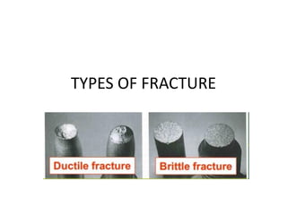
  • 2. Brittle vs. Ductile Fracture • Ductile materials - extensive plastic deformation and energy absorption (“toughness”) before fracture • Brittle materials - little plastic deformation and low energy absorption before fracture. Fracture: Refers to the failure of a material under load by breaking into two or more pieces. Fracture can occur under all service conditions. ➢ Materials subjected to alternating or cyclic loading (as in machines) fail due to fatigue(fatigue fracture) ➢ Materials used at high temperatures can fail due to creep fracture
  • 3. 3 Fracture mechanisms • Ductile fracture – Occurs with plastic deformation • Brittle fracture – Little or no plastic deformation – Catastrophic Ductile Brittle
  • 4. Ductile, Creep Brittle Cracks choose the path of least resistance Brittle fractures display either transgranular or intergranular fracture
  • 5.
  • 6.
  • 7.
  • 8. A. Very ductile, soft metals (e.g. Pb(lead), Au(Aurum-Gold) at room temperature, other metals, polymers, glasses at high temperature. B. Moderately ductile fracture, typical for ductile metals C. Brittle fracture, cold metals, ceramics, ice
  • 9.
  • 10. (a) Necking (b) Formation of microvoids (c) Coalescence of microvoids to form a crack (d) Crack propagation by shear deformation (e) Fracture
  • 11. ➢ Ductile fracture is the rupture of a material after a considerable amount of plastic deformation. ➢ Material begin to neck beyond the ultimate tensile strength ➢ The neck refers to the reduced cross-section of the specimen near the middle.
  • 12. ➢ Cracks are found to nucleate at brittle particles, either the natural kind found in multiphase materials, e.g., cementite in steel, or foreign inclusions, e.g., oxide inclusions in copper. ➢ When a brittle particle is present, it is difficult to maintain compatibility in the neck region between the continuously deforming matrix and the nondeforming particle. This results in the formation of very tiny voids near the matrix-particle interface. ➢ If fracture initiates at pores in the neck region, then the voids are already present. The voids grow with increasing deformation and ultimately reach sizes of the order of a mm. At this stage, the material may tear apart. ➢ This model of ductile fracture is supported by the finding that materials of ultra high purity, which do not have inclusions or pores, do rupture in a fully ductile manner, that is after thinning down to a point or an edge.
  • 13. The basic steps are: void formation, void coalescence (also known as crack formation), crack propagation, and failure, often resulting in a cup-and-cone shaped failure surface.
  • 14. • Evolution to failure: • Resulting fracture surfaces (steel) particles serve as void nucleation sites. Fracture surface of tire cord wire loaded in tension. Moderately Ductile Failure necking s void nucleation void growth and linkage shearing at surface fracture
  • 16. In ductile fracture, extensive plastic deformation takes place before fracture. The terms rupture or ductile rupture describe the ultimate failure of tough ductile materials loaded in tension. Rather than cracking, the material "pulls apart," generally leaving a rough surface. In this case there is slow propagation and an absorption of a large amount energy before fracture. Many ductile metals, especially materials with high purity, can sustain very large deformation of 50–100% or more strain before fracture under favorable loading condition and environmental condition. The strain at which the fracture happens is controlled by the purity of the materials. At room temperature, pure iron can undergo deformation up to 100% strain before breaking, while cast iron or high-carbon steels can barely sustain 3% of strain. Because ductile rupture involves a high degree of plastic deformation, the fracture behavior of a propagating crack as modeled above changes fundamentally. Some of the energy from stress concentrations at the crack tips is dissipated by plastic deformation before the crack actually propagates.
  • 17.
  • 18.
  • 20.
  • 21.
  • 22. Ductile vs Brittle Failure Very Ductile Moderately Ductile Brittle Fracture behavior: Large Moderate Small • Ductile fracture is usually desirable! Ductile: warning before fracture Brittle: No warning
  • 23. 23 • Ductile failure: --one piece --large deformation Example: Failure of a Pipe • Brittle failure: --many pieces --small deformation
  • 24. Ductile vs. Brittle Failure cup-and-cone fracture brittle fracture
  • 25. Since brittle fracture is most unpredictable, usually a notch will be introduced to simulate the conditions. Notch-impact testing
  • 26. 26 Impact Testing final height initial height (Charpy)
  • 27.
  • 28. Two standard tests, the Charpy and Izod, measure the impact energy (the energy required to fracture a test piece under an impact load), also called the notch toughness.
  • 29. DBTT
  • 30. Fracture toughness is a property which describes the ability of a material containing a crack to resist fracture, and is one of the most important properties of any material for many design applications. Fracture toughness is a quantitative way of expressing a material's resistance to brittle fracture when a crack is present. If a material has much fracture toughness it will probably undergo ductile fracture. Brittle fracture is very characteristic of materials with less fracture toughness. An impact toughness versus temperature graph for a steel is shown in the image. It can be seen that at low temperatures the material is more brittle and impact toughness is low. At high temperatures the material is more ductile and impact toughness is higher. The transition temperature is the boundary between brittle and ductile behavior and this temperature is often an extremely important consideration in the selection of a material.
  • 31. Greater the impact energy, the more ductile the material. copper remains ductile at all temperatures in the range covered by this experiment FCC metals remain ductile down to very low temperatures (Cu, Ni)
  • 32. ➢It can be seen that copper remains ductile at all temperatures in the range covered by this experiment. ➢Nylon can be seen to be going through its glass transition at above 50 °C, and hence shows a brittle to ductile transition. ➢In contrast, acrylic remains brittle, as seen from the consistently low impact energies. ➢Zinc becomes more ductile at temperatures above room temperature. ➢Mild steel shows a ductile-brittle transition at around -60 °C. ➢Results for aluminium show that it become slightly less ductile as the temperature is increased, and all the values for impact energy lie between the ductility of copper and the brittleness of acrylic. Flow is always easier than cleavage in aluminium so there is never a ductile-brittle transition observed. The decrease of overall ductility with temperature seen in aluminium arises from dynamic recovery.
  • 33. 33 • Pre-WWII: The Titanic • WWII: Liberty ships • Problem: Used a type of steel with a DBTT ~ Room temp. Design Strategy: Stay Above The DBTT!
  • 34. 34 Engineering Fracture Design • Avoid sharp corners! s r , fillet radius w h o smax
  • 35. Ship-cyclic loading from waves. FATIGUE
  • 36. Computer chip-cyclic thermal loading. Hip implant-cyclic loading from walking. Fatigue Failure Fatigue is the weakening of a material caused by repeatedly applied loads. It is the progressive and localized structural damage that occurs when a material is subjected to cyclic loading. The nominal maximum stress values that cause such damage may be much less than the strength of the material typically quoted as the ultimate tensile stress limit, or the yield stress limit. Fatigue occurs when a material is subjected to repeated loading and unloading.
  • 38.
  • 39.
  • 41.
  • 42. Fatigue Fatigue is caused by repeated application of stress to the metal. It is the failure of a material by fracture when subjected to a cyclic stress. Fatigue is distinguished by three main features. i) Loss of strength ii) Loss of ductility iii) Increased uncertainty in strength and service life This type of failure occurs in Metals and Polymers, While Ceramics do not undergo this type of failure!!
  • 43. Fatigue is an important form of behavior in all materials including metals, plastics, rubber and concrete. All rotating machine parts are subjected to alternating stresses. Example: aircraft wings are subjected to repeated loads, oil and gas pipes are often subjected to static loads but the dynamic effect of temperature variation will cause fatigue. Because of the difficulty of recognizing fatigue conditions, fatigue failure comprises a large percentage of the failures occurring in engineering. To avoid: stress concentrations, rough surfaces and tensile residual stresses, fatigue specimens must be carefully prepared.
  • 44.
  • 45. Fatigue – Stress patterns • Three different fluctuating stress- time modes are possible: (i) Reversed stress cycle, (ii) Repeated stress cycle, (iii) Random stress cycle.(Irregular stress)
  • 46. Stress cycles that can cause fatigue failure are characterized by following parameters:
  • 47. Mean Stress affects Fatigue Life Note, Mean σm = 0, for Reverse stress cycling. Mean σm = +ve quantity for Repeat stress cycling Mean (σm) has an effect on fatigue life. Increasing the mean stress level leads to a decrease in fatigue life.
  • 48.
  • 49. Crack Initiation and Propagation The process of fatigue failure is characterized by three distinct steps: (1) Crack initiation: Cracks always nucleate on the surface of a component at some point of stress concentration. Crack nucleation sites: surface scratches, sharp fillets, keyways, threads, dents, and the like… (2) Crack Propagation: Crack advances incrementally (during this step) with each stress cycle (3) Failure: Failure occurs very rapidly once the advancing crack has reached a critical size.
  • 50. Fatigue Testing – The S-N Curve • Fatigue testing is carried out using standard machines, to simulate the real service conditions: (i) Stress level, (ii) Time-frequency, (iii) Stress pattern.
  • 51. Rotating Beam test specimen, post test with crack
  • 52. Specimen: ASTM E466 standards Reverse bending type fatigue testing machine
  • 53.
  • 54.
  • 55. Stress (MPa) No.of cycles to failure 30 9500000 60 4000000 90 2000000 120 850000 140 600000 30 9400000 60 4000000 90 2100000 120 840000 140 595000
  • 56. Fatigue Testing – The S-N Curve • Fatigue Limit (Endurance Limit): For some steels and Ti alloys, the S-N curve becomes horizontal at higher ‘N’ values for a limiting stress, below which fatigue failure does not occur. For steels, fatigue limit range between 35% and 60% of the tensile strength. • Fatigue strength: Non-ferrous alloys (Al, Cu, Mg) do not have Fatigue Limit. Fatigue strength is defined as the stress level at which failure will occur for some specified number of cycles (e.g, 107 cycles).
  • 57. Fatigue Testing – The S-N Curve • Fatigue Life: Number of cycles to cause failure at a specified stress level, as taken from the S-N plot.
  • 58. The S-N Curve A very useful way to visual the failure for a specific material is with the S-N curve. The “S-N” means stress verse cycles to failure, which when plotted using the stress amplitude on the vertical axis and the number of cycle to failure on the horizontal axis. An important characteristic to this plot as seen is the “fatigue limit”.
  • 59.
  • 60.
  • 61. ➢ The point at which the curve flatters out is termed as fatigue limit and is well below the normal yield stress. ➢ The significance of the fatigue limit is that if the material is loaded below this stress, then it will not fail, regardless of the number of times it is loaded. ➢ Materials such as aluminium, copper and magnesium do not show a fatigue limit; therefore they will fail at any stress and number of cycles. ➢ Other important terms are fatigue strength and fatigue life. ➢ The fatigue strength can be defined as the stress that produces failure in a given number of cycles usually 107. ➢ The fatigue life can be defined as the number of cycles required for a material to fail at a certain stress.
  • 62. Fracture surface of a rotating steel shaft that experienced fatigue failure of metals. Benchmark ridges are visible to the unaided eye as shown in the photograph. Striations: Each bench mark will contain many striations which can be seen using SEM. Crack Initiation and Propagation
  • 63. TEM showing fatigue STRIATIONS in Al. Note presence of striations and benchmark ridges confirm that the failure is fatigue.
  • 64. Fatigue failure of metal surface. A crack formed at the top edge. The smooth region also near the top corresponds to the area over which the crack propagated slowly. Dull and fibrous fracture surface reveals fracture was rapid.
  • 65.
  • 66. Failure can be recognized by the appearance of fracture. For a typical fracture ,Two distinct zones can be distinguished – a smooth zone near the fatigue crack itself which, has been smoothened by the continual rubbing together of the cracked surfaces, and a rough crystalline- looking zone which is the final fracture. Occasionally fatigue cracks show rough concentric rings which correspond to successive positions of the crack.
  • 67.
  • 68. Fatigue life improves by incorporating rounded fillet into a rotating shaft at the point where there is a change in diameter. (a) No fillet; bad design. (b) Fillet provided; good design.
  • 69. Factors affecting fatigue properties Surface finish: Scratches dents identification marks can act as stress raisers and so reduce the fatigue properties. Electro-plating produces tensile residual stresses and have a detrimental effect on the fatigue properties. Temperature: As a consequence of oxidation or corrosion of the metal surface increasing, increase in temperature can lead to a reduction in fatigue properties.
  • 70. Residual stresses: Residual stresses are produced by fabrication and finishing processes. Residual stresses on the surface of the material will improve the fatigue properties. Heat treatment: Hardening and heat treatments reduce the surface compressive stresses; as a result the fatigue properties of the materials are getting affected. Stress concentrations: These are caused by sudden changes in cross section holes or sharp corners can more easily lead to fatigue failure. Even a small hole lowers fatigue-limit by 30%. Factors affecting fatigue properties
  • 71. Fatigue fracture results from the presence of fatigue cracks, usually initiated by cyclic stresses, at surface imperfections such as machine marking and slip steps. The initial stress concentration associated with these cracks are too low to cause brittle fracture they may be sufficient to cause slow growth of the cracks into the interior. Eventually the cracks may become sufficiently deep so that the stress concentration exceeds the fracture strength and sudden failure occurs. The extent of the crack propagation process depends upon the brittleness of the material under test. In brittle materials the crack grows to a critical size from which it propagates right through the structures in a fast manner, whereas with ductile materials the crack keeps growing until the remaining area cannot support the load and an almost ductile fracture suddenly occurs. Fatigue Failure
  • 72. To secure satisfactory fatigue life ▪ Modification of the design to avoid stress concentration eliminating sharp recesses and severe stress raisers. ▪ Precise control of the surface finish by avoiding damage to surface by rough machining, punching, stamping, shearing etc. ▪ Control of corrosion and erosion or chemical attack in service and to prevent of surface decarburization during processing of heat treatment. ▪ Surface treatment of the metal. The endurance limit for the material will be approximately 45 to 50% of the UTS if the surface of the test specimen is smooth and polished.
  • 73. 1. Small scratches, tool marks on surface will limit the fatigue life. 2. Improving the surface- finish by polishing will enhance fatigue life. 3. Residual compressive stresses are introduced into ductile metals mechanically by localized plastic deformation, with in the outer surface region by Shot peening. Shot Peening
  • 74. Case hardening improves fatigue life Case hardening with carbon or nitrogen increases the hardness of the surface for steels. The increased hardness of the case improves the wear resistance and fatigue life.
  • 75. PHYSICAL METALLURGY AND MATERIALS ENGINEERING Hall-Petch equation: Yield stress is inversely proportional to the square root of grain diameter (grain size). Where, σy, is yield stress; σ0 and ky are material dependent constants; d, is grain diameter (grain size). 𝝈 𝒚 = 𝝈 𝟎 + 𝒌 𝒚 𝒅
  • 76. Equicohesive Temperature 1. Strength of the GB = Strength of Grain at the ECT 2. Below ECT fine grain sized material is stronger due to large number of grain boundaries are present. 3. Above ECT large grain sized material is stronger due to less tendency for grain boundary sliding.
  • 77. FAILURE DUE TO TORSION
  • 78. Until the advent of variable speed drives (VSDs), torsional fatigue failures were rare: Equipment designers could anticipate operating speeds and excitation frequencies and engi-neer around them. The purpose of a VSD is to allow operation at a wide range of speeds. That, unfortunately, has led to many motor and driven-shaft failures due to torsional-fatigue factors. While the most common torsional fatigue cracks start at the sharp corner (stress concentration) at the bottom of the keyway when couplings are poorly fitted, another common appearance is the diagonal shaft crack
  • 79.
  • 80.
  • 81.
  • 82.
  • 83. PREVENTING TORSIONAL FATIGUE FAILURES Torsional fatigue failure prevention: Correct machining, assembly and installation to eliminate: ➢Incorrect fit/finish of a shaft and bore. ➢Small radius in a keyseat. ➢Excess clearance between the key and keyseat. ➢Misalignment. These are the easiest to fix. Frequently, the effort stops here and the failures continue. However, with more investigation, torsional fatigue failures can be eliminated.