

Empfohlen
Weitere ähnliche Inhalte
Was ist angesagt?
Was ist angesagt? (20)
Andere mochten auch
Andere mochten auch (20)
Ähnlich wie Nav Topic 9 vhf omni range (vor)
Ähnlich wie Nav Topic 9 vhf omni range (vor) (20)
Mehr von Izah Asmadi
Mehr von Izah Asmadi (20)
Kürzlich hochgeladen
Kürzlich hochgeladen (20)
Nav Topic 9 vhf omni range (vor)
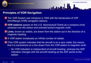
- 1. Malaysian Institute of Aviation Technology FOR TRAINING PURPOSE ONLY Principles of VOR Navigation The VOR System was introduce in 1945 with the introduction of VHF OmniRange (VOR) navigation stations. VOR stations appear on the U.S. Aeronautical Charts as a compass circle centered over the station and oriented toward magnetic north. Lines, known as radials, are drawn from the station out in the direction of a magnetic heading. A VOR station broadcasts an infinite number of radials. If the VOR system indicates that the aircraft is on a zero radial, this means that it is somewhere on a line drawn from the VOR station to magnetic north. – So VOR indication is independent of aircraft heading, whereas the ADF indication changes with the aircraft heading as the ADF points to the station. Subj Code:AFD31202 ect I ssue No :000
- 2. Malaysian Institute of Aviation Technology VOR station shown on aeronautical chart I ssue No :000 FOR TRAINING PURPOSE ONLY Subj Code:AFD31202 ect
- 3. Malaysian Institute of Aviation Technology FOR TRAINING PURPOSE ONLY The principle of VOR operation is based on the generation of radials, or magnetic bearings, by a ground station transmitter and their reception by an airborne receiver. The receiver instrumentation unit determines which radial is passing through the aircraft position. The determined radial is the angle between magnetic north and the aircraft as measured from the ground station. The magnetic course from the aircraft when flying inbound to the station is the reciprocal of the radial Subj Code:AFD31202 ect I ssue No :000
- 4. Malaysian Institute of Aviation Technology VOR radials and magnetic courses I ssue No :000 FOR TRAINING PURPOSE ONLY Subj Code:AFD31202 ect
- 5. Malaysian Institute of Aviation Technology FOR TRAINING PURPOSE ONLY VOR stations operate in the VHF frequency range from 108.00 MHz to 117.95 MHz – therefore limited to line-of-sight navigation – an aircraft flying at an altitude of 20,000 feet should be able to receive VOR stations from as far as 200 miles away The VOR stations are identified by the transmission of a three-letter Morse code group sent 10 times each minute. In some cases, voice identification is added immediately following the Morse code signal. A pilot determines the aircraft's bearing to or from a VOR station by: – first selecting the frequency of the desired station – then turning the omnibearing selector (OBS) until the "left/right' needle on the course deviation indicator (CDI) centers. Subj Code:AFD31202 ect I ssue No :000
- 6. Malaysian Institute of Aviation Technology FOR TRAINING PURPOSE ONLY The reading on the OBS will indicate the radial of the aircraft is on regardless of its heading. A "to/from" arrow is provided on the CDI for determining if the indicated bearing is to or from the station and a warning "flag" will appear if the information is unusable. The VOR and the localizer portion of the instrument landing system operate in the same frequency range – one VHF navigation receiver is used for both functions. Usually, the VOR and localizer circuitry will be found in the same chassis as the VHF navigation receiver. If the VOR and localizer circuitry is contained within the instrument, the combination is known as a converter-indicator. In light aircraft using panel-mounted equipment, the VHF navigation receiver is sometimes located in the same chassis as the VHF communications transceiver. Subj Code:AFD31202 ect I ssue No :000
- 7. Malaysian Institute of Aviation Technology FOR TRAINING PURPOSE ONLY VOR Navigation Concepts The concept of VOR navigation is based on: – detection two distinct signals contained within one carrier signal transmitted from a VOR ground station, and – comparing the phase difference between them to derive the bearing from the station This concept is analogous to a tower having a sharply focused beacon light which rotates at a constant speed, and a second light which flashes in all directions (omni-directional) when the rotating beacon points to magnetic north. The bearing from the tower can thus be determined by multiplying the speed of the rotating beacon by the time required between when the fixed (reference) light flashes and the rotating (variable) light passes by the observer. Subj Code:AFD31202 ect I ssue No :000
- 8. Malaysian Institute of Aviation Technology FOR TRAINING PURPOSE ONLY VOR Navigation Concepts (cont’d) A VOR station radiates a composite electromagnetic field from two ground-based antennas on the same carrier frequency. The first antenna is omni-directional and radiates an amplitude-modulated reference signal. – The modulation frequency of the reference-phase signal varies from 9,480 Hz to 10,440 Hz at a rate of 30 times per second. – The resultant reference-phase signal then consists of a 9,960-Hz subcarrier, frequency-modulated at 30 Hz, that amplitude-modulates the RF carrier. Subj Code:AFD31202 ect I ssue No :000
- 9. Malaysian Institute of Aviation Technology FOR TRAINING PURPOSE ONLY VOR Navigation Concepts (cont’d) The second antenna is a horizontal dipole which rotates at the rate of 1,800 revolutions per minute (30 revolutions per second) and produces a figureeight electromagnetic field pattern. – The RF field within one of the lobes is exactly in phase with the RF radiated from the omni-directional field. – The in-phase lobe extends the omni-directional pattern on one side that result in a cardioids field pattern which rotates at the rate of 30 revolutions per second. Subj Code:AFD31202 ect I ssue No :000
- 10. Malaysian Institute of Aviation Technology FOR TRAINING PURPOSE ONLY VOR Navigation Concepts (cont’d) The airborne VOR receiver detects the RF carrier whose amplitude is varying at a rate of 30 Hz due to the rotation of the cardioids pattern. The carrier is also amplitude-modulated by the 9,960-Hz reference-phase signal, which is frequency-modulated at 30 Hz on a subcarrier to distinguish it from the 30-Hz variable-phase signal. The VOR airborne receiver detects the variable and reference-phase signals and compares their phase difference to determine the aircraft's bearing. At magnetic north, both signals appear in phase. Subj Code:AFD31202 ect I ssue No :000
- 11. Malaysian Institute of Aviation Technology FOR TRAINING PURPOSE ONLY VOR System Operation The VOR station produces the radial pattern by transmitting 30-Hz reference signals and 30-Hz variable-phase signals for comparison by the airborne receiver. The 30-Hz variable-phase signal is an amplitude-modulated component of the VOR station RF signal. – This signal is generated by rotating the transmitting antenna pattern, either mechanically or electronically, at 30 revolutions per second. The station identification code and voice transmissions are also amplitudemodulated components of the signal. The sum of all modulation components from the station results in a maximum of 90% modulation equally divided between the reference-phase component, variable-phase component, and the remaining voice or code identification component. Subj Code:AFD31202 ect I ssue No :000
- 12. Malaysian Institute of Aviation Technology FOR TRAINING PURPOSE ONLY VOR System Operation (cont’d) Magnetic north is the reference for all VOR measurements. – At magnetic north, the 30-Hz variable signal is in phase with the 30-Hz reference signal. At all other radials, the 30-Hz variable signal lead or lag the 30Hz reference signal by the number of degrees from magnetic north to the radial. For example, at 180o from magnetic north, the variable signal is 180o out-of-phase with the reference signal. VOR phase relationships Subj Code:AFD31202 ect I ssue No :000
- 13. Malaysian Institute of Aviation Technology FOR TRAINING PURPOSE ONLY VOR System Operation (cont’d) Figure on the right-side illustrates the phase relationship of the 30-Hz reference and variable signals for an aircraft flying to a VOR station on the 260o radial. The 30-Hz reference component is applied to an FM detector that produces a 30-Hz reference signal: – positive when the subcarrier frequency is high (10,440 Hz) – negative when the frequency is low (9,480 Hz) Phase relationships of a 260o VOR radial Subj Code:AFD31202 ect I ssue No :000
- 14. Malaysian Institute of Aviation Technology FOR TRAINING PURPOSE ONLY Subj Code:AFD31202 ect I ssue No :000
- 15. Malaysian Institute of Aviation Technology FOR TRAINING PURPOSE ONLY VOR System Operation (cont’d) The 30-Hz variable component is applied to an AM detector that produces a 30-Hz variable-phase signal: – positive when the major lobe of the radiated signal is toward the aircraft When the 30-Hz variable and reference phases are compared, the difference is a direct measure of bearing from the VOR station to the aircraft (in this case, 260o). Phase relationships of a 260o VOR radial Subj Code:AFD31202 ect I ssue No :000
- 16. FOR TRAINING PURPOSE ONLY Malaysian Institute of Aviation Technology VOR System Operation (cont’d) The VOR circuitry derives to/from bearing information and left/right deviation from the selected course: – by comparing the received bearing with the setting of the omnibearing selector. An aircraft flying inbound to a VOR station on the 260o radial requires the pilot to slew the OBS to the 80o magnetic course setting. Flying a VOR radial Subj Code:AFD31202 ect I ssue No :000
- 17. Malaysian Institute of Aviation Technology FOR TRAINING PURPOSE ONLY VOR System Operation (cont’d) Since the 80o selected magnetic course is displaced by more than 90o from either side of the VOR radial, the to/from arrow points upwards indicating the aircraft is flying to the station. The VOR circuitry produces left/right course deviation information in a manner similar to to/from deviation. When the OBS is set at 80o, a deviation window of approx. plus or minus 10o (full scale on the left/right deviation bar on the CDI) is formed symmetrically around the 260o VOR radial. Subj Code:AFD31202 ect I ssue No :000
- 18. Malaysian Institute of Aviation Technology FOR TRAINING PURPOSE ONLY VOR System Operation (cont’d) The VOR circuitry compares the selected OBS magnetic course with the received VOR radial and positions the course deviation indicator bar to indicate the direction, – the pilot must turn the aircraft to intercept the desired radial Thus, the deviation bar indicates where the selected VOR radial is located with respect to the aircraft's position. The pilot keeps from deviating from the selected course by following the command of the left/right deviation bar to maintain the bar in the center position. Subj Code:AFD31202 ect I ssue No :000
- 19. Malaysian Institute of Aviation Technology FOR TRAINING PURPOSE ONLY VOR Transceiver System VHF omnirange (VOR) is an electronic navigation system that enables a pilot to determine the bearings of the VOR transmitter from any position in its service area. – This is possible because the VOR ground station, or transmitter, continually broadcasts an infinite number of directional radio beams or radials. The VOR signal received in an airplane is used to operate a visual indicator from which the pilot determines the bearings of the VOR station with respect to the airplane. Subj Code:AFD31202 ect I ssue No :000
- 20. Malaysian Institute of Aviation Technology FOR TRAINING PURPOSE ONLY Omni bearing indicator Subj Code:AFD31202 ect I ssue No :000
- 21. Malaysian Institute of Aviation Technology FOR TRAINING PURPOSE ONLY Subj Code:AFD31202 ect I ssue No :000 Block diagrams of VOR transmitter and receiver systems
- 22. Malaysian Institute of Aviation Technology FOR TRAINING PURPOSE ONLY VOR Transceiver System (cont’d) The diagram for the VOR ground station, or transmitter, shows a five-unit antenna array. The center loop of the antenna array continuously broadcasts the reference phase signal, which is modulated at 30 Hz. Two outputs are radiated by the diagonal pairs of comer antennas, – the signals radiated from these pairs are modulated by 30 Hz and differ in phase by 90o Each pair of antennas radiates a figure-eight pattern, each pattern being displaced from the other by 90o both in space and in time phase. The resulting pattern is the sum of the two figure eight patterns and consists of a rotating field turning at 1800 rpm, or 30 Hz. Subj Code:AFD31202 ect I ssue No :000
- 23. Malaysian Institute of Aviation Technology FOR TRAINING PURPOSE ONLY VOR Transceiver System (cont’d) The total effect of the radiation from the VOR transmitter is to produce two signals whose phase characteristics vary in accordance with the direction (bearing) of the transmitter from the receiver. The two signals radiated due south (magnetic) of the transmitter are exactly in phase; – hence an airplane flying magnetic north directly toward the VOR transmitter will show an indicated bearing of 0o to the VOR station. The TO-FROM indicator will show that the airplane is flying to the station. In a clockwise direction around the VOR station, the radiated signals become increasingly out of phase. Subj Code:AFD31202 ect I ssue No :000
- 24. Malaysian Institute of Aviation Technology FOR TRAINING PURPOSE ONLY VOR Transceiver System (cont’d) At 90o clockwise from the due south direction, the signals are 90o out of phase, at 180o they are 180o out of phase; at 270o they are 270o out of phase; and at 360o (0o) they are back in phase. The phase difference of the two signals makes it possible for the receiver to establish the bearings of the ground station. The directional bearings of VOR stations are set up in accordance with the earth's magnetic field so that they may be compared directly with magneticcompass indications on the airplane. During the operation of VOR equipment on a particular heading, an airplane flying toward the VOR station will show a TO indication on the omni-indicator. After the airplane passes the station, the indicator will show FROM, and the heading information will remain the same as it was. Subj Code:AFD31202 ect I ssue No :000
- 25. Malaysian Institute of Aviation Technology FOR TRAINING PURPOSE ONLY VOR Transceiver System (cont’d) For example, if an airplane is flying toward a VOR station having a bearing of 200o the omnibearing indicator will show 200o TO. After the airplane passes over the VOR station, the indicator will show 200o FROM. The carrier frequency of the VOR station is in the VHF range, between 112 and 118 MHz. A modulation of 9960 Hz is placed on the carrier of the reference signal to provide a subcarrier, which is modulated by a 30-Hz signal. The 9960-Hz modulation on the original carrier wave is AM, and the 30-Hz signal on the subcarrier is FM. The carrier wave for the variable-phase signal is amplitude-modulated by a 30Hz signal. Subj Code:AFD31202 ect I ssue No :000
- 26. Malaysian Institute of Aviation Technology FOR TRAINING PURPOSE ONLY VOR Transceiver System (cont’d) The VOR receiver mounted in an airplane may be an independent unit, or it may operate in conjunction with the VHF communication radio. Light aircraft typically use the combined unit, known as a VHF NAV/COM radio. The VOR receiver receives both components of the VOR signal transmitted from the ground station and from these signals produces two 30-Hz signals: – one being the reference phase – the other being the variable phase The angular distance between the two phases is applied to the omnirange indicator, by which it is translated into usable heading information. Subj Code:AFD31202 ect I ssue No :000
- 27. Malaysian Institute of Aviation Technology FOR TRAINING PURPOSE ONLY VOR Transceiver System (cont’d) The onmirange indicator includes an azimuth dial, a LEFT-RIGHT deviation needle, and a TO-FROM indicator. When the VOR receiver on an airplane is tuned to a VOR ground station, the LEFT-RIGHT indicating needle will be deflected either to the right or to the left unless the selected course on the omnirange indicator is in agreement with the bearing of the VOR ground station. Once the pilot has tuned to the correct ground station frequency and selected the correct course, the unit is ready for navigation. For example, if the course-deviation indicator bar moves to the left, the pilot knows the intended course is to the left of the aircraft. To correct the flight path, the pilot must turn the aircraft to the left. Subj Code:AFD31202 ect I ssue No :000
- 28. Malaysian Institute of Aviation Technology FOR TRAINING PURPOSE ONLY VOR Equipments system Operation A VHF navigation receiver operates in the same manner as a VHF communications receiver with the exception that the navigation receiver does not incorporate the use of a squelch circuit to disable the audio output when the signal strength is below a certain threshold setting. The audio output must be made available to the VOR converter or instrumentation unit at all times in order for it to derive navigational information from the composite VOR signal. The sensitivity of a typical superheterodyne navigation receiver will cause a three microvolt input signal modulated at 30% with a 1,000-Hz tone to produce 200 milliwatts output with a six dB signal-to-noise ratio. An automatic gain control is used to maintain not more than a three dB variation over a 5 millivolt to 50,000 millivolt input signal range. Subj Code:AFD31202 ect I ssue No :000