[Webinar] SpiraTest - Setting New Standards in Quality Assurance
Ultrasound
1. PART (2): PROPERTIES OF SOUND
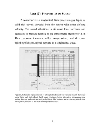
A sound wave is a mechanical disturbance in a gas, liquid or
solid that travels outward from the source with some definite
velocity. The sound vibrations in air cause local increases and
decreases in pressure relative to the atmospheric pressure (Fig.1).
These pressure increases, called compressions, and decreases
called rarefactions, spread outward as a longitudinal wave.
Figure1. Schematic representation of a longitudinal sound wave at one instant. 'Particles'
move back and forth about fixed mean positions, being alternately compressed and
pushed forward and stretched and pulled back. The pressure variations are passed from
one layer of particles to the next at the speed of sound c.
1
2. Wherever the density or compressibility of tissue changes in
the path of an ultrasonic wave, echoes are sent back to the
ultrasound probe. These may be weak reflections from the
interfaces between different tissues, or even weaker scatter from
the numerous small scale structures within tissue. In most
applications, the diagnostic information from an ultrasound scan
comes from scattered echoes rather than from echoes reflected
from larger interfaces. Fortunately, ultrasound pulses travel at a
fairly constant speed along narrow pencil beams, so that the
direction and range of echo sources can be measured and plotted.
However,
distortions
and
artifacts
do
occur,
and
some
understanding of the basic physics of sound propagation and of the
techniques used in scanning equipment is necessary, if high quality
scans are to be produced and their limitations appreciated.
Speed of sound
The speed with which the pressure disturbances (both
positive and negative) travel away from the source is known as the
speed of sound (c). The speed of sound is a constant for any
medium and is completely determined by the density () and
compressibility of the medium. It does not, therefore, depend on
the frequency of the wave. The relevant measure of compressibility
is the bulk modulus of elasticity (k), which is the ratio of the
pressure applied to a fixed mass of medium to the fractional
2
3. change in volume. It is high for relatively incompressible media
such as solids, water or tissues, but low for compressible media
such as gases. The speed of sound may be expressed in terms of k
and p by:
In practice, tissues differ much more in compressibility than
in density, so that bone (very incompressible, high k) has a higher
speed of sound than muscle, despite the fact that it is more dense.
The mean value of the speed of sound in soft tissue is generally
taken to be 1540 m s-1.
Energy, power and intensity
The source does work and gives energy to the first layer of
particles of the medium as it pushes and pulls them. This energy is
passed from particle to particle as the wave propagates, eventually
being absorbed as heat. A single ultrasound pulse from a
diagnostic scanner leaving the probe might typically carry with it a
few microjoules (µJ) of energy. Over any specified time period,
any source of ultrasound will transmit a certain amount of energy.
Power is the rate at which energy is transferred, its unit being the
watt (W), where 1 watt equals 1 joule per second. The rate of
working by the source, and hence the transmitted acoustic power,
3
4. varies from instant to instant. The instantaneous acoustic power is
zero when the source momentarily stops and changes direction,
and reaches its peak when it is pushing the adjacent medium
forwards, or pulling it backwards, at maximum speed. The
temporal average acoustic output power of the source is the total
energy transferred from the source to the medium in every second.
This may be up to a few hundred mW for a medical diagnostic
scanner, which might typically transmit a few thousand pulses per
second.
A quantity that is often of more interest than power is
acoustic intensity. This is a measure of the local concentration of
power, and is defined as the energy flow per unit area per second,
or the power per unit area (assuming the area considered is
perpendicular to the direction of travel of the wave). Although
defined in terms of an area, intensity describes the situation at a
point. It equals the power that would be measured passing through
a tiny area centred on the point, divided by that area. Strictly the SI
unit of intensity is a watt per square meter (W m-2), but ultrasound
intensities are usually quoted in W cm-2 or mW cm-2.
The intensity (I) of a sound wave is the energy passing
through unit area in unit time, i.e.
4
5. For a plane wave I is given by:
Where is the density of the medium; v is the velocity of sound; f
is the frequency; is the angular frequency, which is equal to 2πf;
A is the amplitude of the wave or the maximum displacement of
the molecules from the equilibrium position; and Z, which equals
v, is the acoustic impedance of the medium. Some typical values
of , v, and Z are given in Table 1 . The intensity can also be
expressed as:
Where Po is the maximum acoustic pressure.
Table1. Values of , v, and Z for various substances
5
6. The Decibels Scale :
A special unit, the bel, has been developed for comparing the
intensities of two sound waves (I2/I1), two powers or two energies.
This unit was named after Alexander Graham Bell, who invented
the telephone and did research in sound and hearing. The intensity
ratio in bels is equal to log10 (I2/I1) or equal to 10 log10 (I2/I1) in
decibels, (one bel =10 decibels 'dB').
Number of dB = 10 log10
Since I is proportional to P, that is, I2/I1 =
hence, the
pressure ratio between two sound levels can be expressed as
Number of dB = 10 log10
= 20 log10
This Expression can lie used to compare any two sound pressures
in the same medium.
For hearing test, it convenient to use a reference sound
intensity (or sound pressure) to which other sound intensities (or
sound pressures) can be compared. The reference sound intensity Io
is 10-12 W/m2 and the reference sound pressure pQ is 2 x 10⁻⁵ N/m2.
A 1000 Hz note of this intensity is barely audible to person with
good hearing.
6
7. If a sound intensity is given in decibels with no reference to
any other sound intensity, you can assume that Io is the reference
intensity.
Decibels are also used to express the ratio of the amplitudes
of two waves or two electronic signals. As stated above, decibels
are for use with energy or power quantities, so it is actually the
ratio of the powers associated with the two amplitudes that is given
in decibels. It is therefore necessary to square the two amplitudes
before taking the logarithm, since the power associated with an
ultrasonic wave is proportional to the square of the pressure and
the electrical power associated with an electrical voltage is
proportional to the square of the voltage. A mathematically
equivalent alternative to squaring the amplitudes is to use 20
instead of 10 in the dB formula. Thus, if A1 and A2 represent the
two amplitudes
Number of dB = 10 log10
= 20 log10
Pulse waves, energy spectra and bandwidth
The pulses used in medical ultrasound generally have a
length of only about 2 cycles (figure 2(a)). Typically, peak positive
and negative pressures are up to about a megapascal (MPa) or so.
7
8. The peak back and forth displacements of particles are inversely
proportional to frequency.
Strictly, only a continuous wave can be characterized by a
single frequency. A plot of amplitude versus frequency is known
as the amplitude spectrum of the pulse. Since energy is
proportional to the square of amplitude, the energy spectrum
(figure 2(b)) of the pulse, showing the relative energy at each
frequency, is given by squaring amplitude in the amplitude
spectrum.
Figure 2. Pressure-time waveform of a typical ultrasonic pulse and its energy spectrum.
The pulse centre frequency (f) and the pulse bandwidth are indicated.
8
9. Two useful characteristics of the energy spectrum are the
centre frequency (fc), at which the spectrum has its maximum
height, and the pulse bandwidth, which is defined as the width of
the energy spectrum at half its maximum height. An important rule
is that pulse bandwidth increases as pulse length decreases. In
fact:
pulse bandwidth (MHz) =
.
Thus a continuous wave, which might be considered to be a
pulse of constant amplitude and infinite length, has an infinitely
narrow bandwidth (i.e. it has a spectrum consisting of a single
line). For a typical two-cycle imaging pulse, the bandwidth is
about 50% of fc. Thus, a '3 MHz' imaging pulse really means a
pulse with a centre frequency of 3 MHz, but containing substantial
energy at frequencies between about 2.2 MHz and 3.8 MHz.
The Propagation of Ultrasound waves in Tissue
Wave attenuation is the reduction of intensity with distance
from the source. For a wave travelling through the body the causes
of attenuation include divergence of the beam, partial reflection
and rarefaction at tissue interfaces, and absorption and scattering
within individual tissues.
9
10. Reflection:
Wherever an ultrasound wave meets an interface where the
characteristic acoustic impedance changes, a reflected wave is
produced which carries with it a fraction of the power of the
original wave. If the interface is smooth (on the scale of a
wavelength) it is said to be a specular reflector, and behaves in the
same way that a mirror (or partial mirror) reflects light waves. In
particular, the angle of reflection equals the angle of incidence
(figure 4(c)). This has important practical consequences since it
means that where the source of the ultrasound is also the receiver,
as in medical ultrasonic scanning, the wave reflected from a
smooth surface can only be detected if the incident wave is
perpendicular to the surface (figure 4(b)).
For many tissue boundaries, small surface irregularities
produce weak scattered waves over a very wide range of angles.
Such boundaries are described as diffuse reflectors by analogy
with the way that a matt surface or ground glass plate produces
diffuse reflection of light. The echoes they produce on an
ultrasound image are weaker than those from a specular reflector,
but they are much more likely to be registered, as they do not
require that the interface is perpendicular to the incident wave
direction.
10
11. When a sound wave hits the body, part of the wave is
reflected and part is transmitted into the body. The ratio of the
reflected pressure amplitude (Pr) to the incident pressure amplitude
(Pi) is given by:
Where Z1 and Z2 are the acoustic impedances of medium 1 and 2
respectively. If Z1=Z2 , there is no reflected wave and transmission
to the second medium is complete.
Figure 3. A sound wave of amplitude pressure. Pi.
Incident upon the body. Part of the wave, of
amplitude pressure Pr. is reflected and part, of
amplitude pressure Pt is transmitted
The ratio of the transmitted pressure amplitude Pt. to the incident
wave amplitude Pi is given by
11
12. The last two equations are for sound waves striking perpendicular
to the surface.
The ratio of reflected intensity to the total intensity is given by:
The ratio of transmitted intensity to the total intensity is given by:
It is clear that when, the acoustic impedances of the two
media are similar almost all the sound is transmitted into the
second medium. Choosing materials with similar acoustic
impedances is called impedance matching. Getting sound energy
into the body requires impedance matching.
Refraction of Sound Waves :
If an ultrasound wave meets, at an oblique angle, a boundary
between two media having different speeds of sound, the
transmitted wave will be deflected. This is known as refraction,
and is illustrated in figure 4(a). The effect is analogous to that of a
12
13. light beam meeting a glass or water interface. In common with
optics, Snell's law applies:
Here c1 and c2 are the speeds of sound in the first and second
media respectively, and angles are measured from a line (normal)
perpendicular to the boundary. The law shows that the transmitted
beam is deflected further away from the normal when c2 > c1 or
towards the normal (as in figure 4(a)) when c2 < c1. If c2 = c1 or if
the beam strikes the boundary at right angles (regardless of the
values of c2 and c1) then no refraction takes place. In soft tissues,
because variations in the speed of sound are small, beam
deviations are generally only slight, but they are often sufficient to
degrade the image quality and produce image artifacts.
Where the speed changes from a lower to a higher value at
an interface, and the angle of incidence is large, it is possible for
the sine of the angle of transmission, as calculated from Snell's
law, to be greater than 1. Since the sine of a real angle cannot be
more than 1, this means there can be no transmission. The surface
then acts as a complete reflector and the beam undergoes total
internal reflection back into the first medium (4(c)).
13
14. Figure 4. (a) Partial reflection occurs when an ultrasound beam meets the boundary
between two media of different characteristic impedances. If the speed of sound is
different in the two media, as assumed here, the transmitted beam is refracted (ө1≠ ө2).
(b) Perpendicular incidence is assumed in the definition of reflection coefficient, (c) Total
internal reflection occurs if sin ө2 xc2/c1 > 1.
Absorption
When a sound wave passes through tissue, there is some loss
of energy due to frictional effect. The absorption of energy in the
tissue causes a reduction in the amplitude and the intensity of the
incident sound wave. The amplitude (A) at a depth x cm in a
medium is related to the initial amplitude Ao (at x=0) by the
exponential equation:
Where α, in cm-1 is the absorption coefficient for the medium at a
particular frequency.
Since the intensity is proportional to the square of the
amplitude, its dependence with depth is
14
15. Where Io is the incident intensity at x = 0 and I is the intensity at
depth x in the absorber.
Since the absorption coefficient in the last equation is 2α
therefore the intensity decreases more rapidly than the amplitude
with depth.
The half-value thickness (HVT) is the tissue thickness needed to
decrease Io to Io/2 .
Table2 gives typical HVTs for different tissues. Note the high
absorption in the human skull and that the absorption increases as
the frequency of the sound increases
Table 2. Absorption Coefficients and Half-Value Thicknesses for various substances.
15
16. The Stethoscope :
Many sounds from the chest region can be useful in the
diagnosis of disease.
The stethoscope is a simple "hearing aide" permits a physician
to listen to sounds made inside the body, primarily in the heart and
lungs. The act of listening to these sounds with a stethoscope is
called mediate auscultation or usually just auscultation.
The main parts of a modern stethoscope are the bell, which is
either open or closed by a thin diaphragm, the tubing, and the
earpieces (Fig. 5).
The open bell is an impedance matcher between the skin and
the air and accumulates sounds from the contracted area. The skin
under the open bell behaves like a diaphragm. The skin diaphragm
has a natural resonant frequency at which it most effectively
transmits sounds; the factors controlling the resonant frequency
are its tension and the diameter of the bell. The tighter the skin is
pulled, the higher its resonant frequency. The larger the bell
diameter, the lower the skin's resonant frequency. Thus it is
possible to enhance the sound range of interest by changing the
bell size and varying the pressure of the bell against the skin and
thus the skin tension A low frequency heart murmur will appear to
go away if the stethoscope is pressed hard against the skin.
16
17. A closed bell is a bell with a diaphragm of known resonant
frequency, usually high, that tunes out low frequency sounds. Its
resonant frequency is controlled by the same factors that
mentioned above. The closed-bell stethoscope is primarily used for
listening to lung sounds, Which are of higher frequency than heart
sounds.
Figure 4. Most of the heart sounds are of low frequency in the region where the
sensitivity of the ear is poor. Lung sounds generally have higher frequencies. The curve
represents the threshold of hearing for a good ear. Some of the heart and lung sounds are
below this threshold
For the best shape for the bell, it is desirable to have a bell
with as small a volume as possible. The smaller the volume of air,
the greater the pressure change for a given movement of the
diaphragm at the end of the bell.
The volume of the tubes should also be small, and should be
little frictional loss of sound to the walls of the tubes. The small
17
18. volume restriction suggests short, small diameter tubes, while the
low friction restriction suggests large diameter tubes. If the
diameter of the tube is too small, frictional losses occur, and if it is
too large, the moving air volume is too great; in both cases the
efficiency is reduced. A compromise is a tube with a length of
about 25 cm and a diameter of 0.3 cm.
The earpieces should fit snugly in the ear because air leaks
reduce the sounds heard, the lower the frequency, the more
significant the leak. Leaks also allow background noise to enter the
ear.
18