Cardiac CT
•Als PPTX, PDF herunterladen•
102 gefällt mir•24,251 views

This presentation deals with the image reconstruction, technique, artifacts and radiation risk associated with cardiac ct scanning.

Empfohlen
Weitere ähnliche Inhalte
Was ist angesagt?
Was ist angesagt? (20)
Ähnlich wie Cardiac CT
Ähnlich wie Cardiac CT (20)
Mehr von Sudil Paudyal
Kürzlich hochgeladen
Kürzlich hochgeladen (20)
Cardiac CT
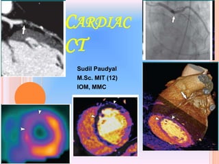
- 1. CARDIAC CT Sudil Paudyal M.Sc. MIT (12) IOM, MMC 1
- 2. INTRODUCTION Coronary artery disease- major cause of death, enormous economic burden on healthcare. Prime diagnostic tool- Coronary angiography Invasive Longer examination time Pt. prep time and recouping time. Advent of MDCT technology: sub millimeter spatial resolution, improved temporal resolution and ECG triggered or gated mode of acquisition Non-invasive imaging of heart and coronary arteries. Calcium scoring, CT angiography, and assessment of ventricular function. The American College of Cardiology Foundation and the American College of Radiology formulated recommendations for “the use of CT coronary angiography as an alternative to conventional catheter angiography in the examination of patients who have symptoms but have inconclusive findings at stress ECG or are unable to exercise.” 2
- 3. CARDIAC SCANNERS EBCT: 1982, specifically for cardiac imaging, able to acquire an image in 100 msec, suited for cardiac imaging at that time. Electrons accelerated in a vacuum funnel and are precisely focused toward and swept across a 210º tungsten ring anode placed under the patient. A cone beam of X-ray photons is emitted which go through the patient and are captured by two 240º detector rows above the patient. Slice collimation is 3 mm, so 40 slices needed to cover the entire heart (12 cm),for a total imaging time of 30 sec. One breath-hold. ECG-based triggering used for motion-free imaging during diastole. Significant motion artifacts still remain. 3
- 4. The spectrum of applications limited, and its physical setup cumbersome. Mostly used for noninvasive evaluation of coronary artery calcium but other applications including assessment of coronary artery stenosis have been reported in limited cases. Expensive and widely not available. 4
- 5. SSCT: Single-slice helical CT could be used for cardiac imaging with ECG-synchronized protocols. Temporal resolution was improved over nonhelical scanners but, remained insufficient for motion-free cardiac imaging. Could not meet unique demands of imaging the beating heart require optimal spatial resolution, temporal and contrast resolution. MDCT:. submillimeter spatial resolution (0.75 mm), improved temporal resolution (80–200 msec), and electrocardiographically (ECG) gated or triggered mode of acquisition, MDCT scanners (16–64-row detectors) makes cardiac imaging possible. 5
- 6. KEY ISSUES IN CARDIAC IMAGING High temporal resolution Virtually “freeze” the beating heart to image coronary arteries located close to heart muscles, which show rapid movement during cardiac cycle. Imaging is best if performed in diastole phase- most quiescent part of cardiac cycle. ECG continuously recorded for synchronisation with image acquisition and reconstruction. High spatial resolution- resolve very fine structures eg. proximal coronary segments which range from a few mm in diameter (at the apex of aorta) and decrease to a few submm in diameter as they traverse away from aorta in all directions. 6
- 7. Diastolic phase narrows with increasing heart rate. 7
- 8. Desired temporal resolution : 250 ms for heart rates upto 70 bpm Upto 150 ms for heart rates greater than 100 bpm Ideally around 50 ms for motion free imaging Standard of reference for comparing temporal resolution is fluoroscopy, wherein motion is frozen during dynamic imaging to a few ms (1-10 ms). Sufficient CNR- to resolve small and low contrast structures such as plaques. CT- excellent low contrast resolution. But can degrade with the increasing number of CT detectors in the z- direction due to increased scatter radiation. 8
- 9. CORONARY ARTERY Coronary artery is a vasa vasorum that supplies the heart. The coronary artery arises just superior to the aortic valve and supply the heart The aortic valve has three cusps – left coronary (LC), right coronary (RC) posterior non-coronary (NC) cusps. 9
- 10. Originates from right coronary sinus of Valsalva Courses through the right AV groove between the right atrium and right ventricle to the inferior part of the septum 10 RIGHT CORONARY ARTERY
- 11. 11 Right coronary artery Conus artery Sinu nodal artery Marginal artery Post. Descending IV artery AV nodal artery- Conus branch SINU NODAL BRANCH AV Nodal Branch BRANCHES OF RCA
- 12. Conus branch – 1st branch supplies the RVOT Sinus node artery – 2nd branch - SA node.(in 40% they originate from LCA) Acute marginal arteries-Arise at acute angle and runs along the margin of the right ventricle above the diaphragm. Branch to AV node Posterior descending artery : Supply lower part of the ventricular septum & adjacent ventricular walls. Arises from RCA in 85% of case. 12
- 13. Right coronary anatomy AO LA RCA CONUS BR RCA SAN 1 2 3 4 RCA AM 13
- 14. RCA AM AM 14
- 15. AREA OF DISTRIBUTION RT CORONARY ARTERY: 1)Right atrium 2)Ventricles i) greater part of rt. Ventricle except the area adjoining the anterior IV groove. ii) a small part of the lt ventricle adjoining posterior IV groove. 3)Posterior part of the IV septum 4)Whole of the conducting system of the heart, except part of the left br of AV bundle 15
- 16. Arises from left coronary cusps Travels between RVOT anteriorly and left atrium posteriorly. Almost immediately bifurcate into left anterior descending and left circumflex artery. Length – 10-15mm 16 LEFT CORONARY ARTERY
- 17. Left coronary artery LAD Diagonal artery Lt Conus artery Anterior Septal br Circumflex artery Obtuse marginal branches Ventricular branches Atrial rami 17
- 18. LEFT CORONARY ARTERY 18
- 19. AREA OF DISTRIBUTION LT CORONARY ARTERY 1) Left atrium. 2) Ventricles i) Greater part of the left ventricle, except the area adjoining the posterior IV groove. ii) A small part of the right ventricle adjoining the anterior IV groove. 3) Anterior part of the IV septum. 4) A part of the left br. Of the AV bundle. 19
- 20. 20
- 21. DOMINANCE Determined by the arrangement that which artery reaches the crux & supply posterior descending artery The right coronary artery is dominant in 85% cases. 8% cases - circumflex br of the left coronary artery 7% both rt & lt coronary artery supply posterior IVseptum & inferior surface of the left ventricle- codominance 21
- 22. SOME PHYSICS TEMPORAL RESOLUTION Number of factors influence the temporal resolution Gantry rotation time Acquisition mode Type of image recon Pitch Gantry rotation time: amount of time reqd. to complete one full rotation (360) of the tube and detector around the pt. Advances in technology have decreased this time to as low as 330-370 ms (250 ms nowadays). Faster gantry rotation, greater temporal resolution Incresased gantry rotation, increase in stress on gantry structure because of higher G forces. (mechanical stress caused by heavy equipments) 22
- 23. Acquisition mode: Prospective ECG triggering: Similar to conventional step and shoot method Pt.s cardiac functions are monitored continuously through ECG signals Protocols so built to start exposure at a desired distance from R-R peak. Scanner starts the scan at the preset point in the R-R interval period. Projection data are acquired for only part of the complete gantry rotation ( i.e partial scan). Once the desired data are acquired, table translated to next bed position, and after a suitable and steady heart rate is achieved, acquisition of more projections. This cycle is repeated until entire scan length is covered, typically 12-15cm 23
- 24. 24
- 25. Additional technical effect- As the pt table has to move by the distance covered by multiple slices in between the scans, a technical delay time (so- called scan-cycle time) has to be taken into consideration. The minimum scan-cycle time between two consecutive ECG-triggered scans depends on the table-feed between the two scans and on the acquisition time of one scan. Usual scan-cycle times of modern multi-slice CT scanners are in the range of 0.8–1.5 s Thus, one heart beat has to be skipped in between every scan for usual clinical examinations at heart rates between 50 and 90 bpm with R-R interval times between 0.7 and 1.2 s. 25
- 26. Filters: Two filter techniques used for prospective estimation of position of the following R-wave. mean filtering (e.g., 3 previous RR-intervals) and median filtering (e.g., 5 previous RR-intervals). Median filter approach shows increased robustness for patients with moderate arrhythmia due to the fact that single extra beats are eliminated. 26
- 27. 27 With MDCT, increasing number of detector rows in z-axis allows larger volume coverage. Higher number of slices helpful in minimizing motion artifacts.
- 28. One of the advantages of the prospective triggering approach is reduced radiation exposure, because the projection data are acquired for short periods and not throughout the heart cycle. Temporal resolution with this type of acquisition can range from 200 to 250 msec. Prospective triggering is the mode of data acquisition used for calcium scoring studies, since calcium scoring analysis is typically performed in axial scan mode. The scan technique such as tube current (milliamperes) for a calcium scoring protocol can be quite low, yielding low radiation dose, since calcium has a high CT number and is easily visible even with a noisier background. Also, each data set is obtained during the most optimal ECG signal to reduce motion artifacts. 28
- 29. Retrospective ECG gating: Main choice of data acquisition in MDCT The pt.s ECG signals are monitored continuously and data is acquired continuously (simultaneously) in helical mode. Both the scan projection data and the ECG signals are recorded. The information about the pt.s heart cycle is then used during image reconstruction, which is performed retrospectively, hence the name retrospective gating. The image reconstruction is performed either with data corresponding to partial scan data or with segmented reconstruction. 29
- 30. In segmented reconstruction, data from different parts of the heart cycle are chosen, so that the sum of the segments equates to the minimal partial scan data required for image reconstruction. This results in further improvements in temp resolution. Can range from 80 to 250 msec. The disadvantage is the increased radiation dose, because the data are acquired throughout the heart cycle, even though partial data are actually used in the final image reconstruction. Also, since this scan is performed helically, the tissue overlap specified by the pitch factor is quite low, indicating excessive tissue overlap during scanning, which also increases radiation dose to the patients. 30
- 31. 31
- 32. Retrospective ECG gating Prospective ECG triggering continuous volume coverage and better spatial resolution in the patients' longitudinal direction, as images can be reconstructed with arbitrary, overlapping slice increments is usually restricted to scanning with nonoverlapping adjacent slices or slice increments with only small overlap. in less sensitivity to heart-rate changes during the scan estimation of the next RR-interval may be incorrect when heart-rate changes are present (e.g., arrhythmia, Vasalva maneuver) and scans may be placed in inconsistent heart phases. Faster volume coverage Scan cycle time limits the duration of scan acquisition allows for imaging in a complete cardiac cycle using the same scan data set, thus providing information on cardiac function. targets only one specific phase of the cardiac cycle and requires additional examinations with new breath-hold levels and additional contrast agent to cover more phases of the cardiac cycle. 32
- 33. RECONSTRUCTION METHOD Partial scan: most practical solution is the partial scan Partial scan reconstruction can be used for both prospective triggering and retrospective gating acquisitions. partial-scan fan-beam data set has to cover a projection- angle interval αP (angle interval between tube positions at the start and end points of tube rotation) of 180° plus the breadth of the X-ray fan: αP = π + βf. The breadth of the X-ray fan-beam βf depends strongly on the diameter of the scan field of view (usually 50 cm) and the distances of the focal spot and detector from the center of the scan field of view. 33
- 34. The equation αP = π + βf states that a minimum data segment of 180° has to be available for every fan angle β. Thus, a partial rotation usually covers about two-thirds of a rotation (≈240°). Conventional partial scan reconstruction techniques based on fan-beam geometry make use of all acquired data even if more data than the minimum angle of 180° are available for a fan angle β. These techniques produce a temporal resolution equal to the partial-scan acquisition time (≈two-thirds of the rotation time). Eg. for a gantry rotation of 500 msec, the scan time for acquiring data for partial scan reconstruction is around 260 to 280 msec. To date, the fastest commercially available gantry rotation time is 330 msec. In such scanners, the partial scan reconstruction temporal resolution can be as high as 170–180 msec. The G force generated due to rapid gantry motion is growing exponentially and is reaching a limit for the existing technology. 34
- 35. Better temporal resolution can be achieved with special reconstruction algorithms that use the minimum required amount of scan data. These algorithms, referred to as "half-scan" reconstruction, can be best explained using parallel-beam geometry. The fan-beam geometry of the partial- scan data set is transformed to parallel-beam geometry using "rebinning" techniques. The rebinning of a partial-scan fan-beam data set provides 180° of complete parallel projections, including chunks of incomplete parallel projections that consist of redundant data. Half scan is the method of choice for reconstruction in cardiac applications. 35
- 36. 36
- 37. Multisegment reconstruction: Principle- The scan projection data required to perform a partial scan reconstruction are selected from various sequential heart cycles instead of from a single heart cycle. This is possible only with a retrospective gating technique and a regular heart rhythm. The CT projection data are acquired continuously throughout many sequential heart cycles. For eg; if one chooses to select half of the data set required for partial scan reconstruction from one heart cycle and the rest from another heart cycle, this results in temporal resolution that is about one-fourth of the gantry rotation time. This is done by using projection data from two separate segments of the heartbeat cycle for image reconstruction. Improvement in temporal resolution can be achieved by cleverly selecting projection data from three or four different heart cycles, resulting in temporal resolution as low as 80 msec. 37
- 38. In general,temporal resolution can range from a maximum of TR/2 to a minimum of TR/2M, where TR is the gantry rotation time (seconds), and M is the number of segments in adjacent heartbeats from which projection data are used for image reconstruction. Usually, M ranges from 1 to 4. 38
- 39. 39
- 40. Advantage- Possibility to achieve high temporal resolution. Disadvantage- Because projection data sets are obtained from different heartbeat cycles, a misregistration due to rapid motion can result in the degradation of image spatial resolution. 41
- 41. 42
- 42. SYNCHRONIZATION WITH THE ECG AND CARDIAC MOTION With both prospective ECG triggering and retrospective ECG gating, the starting points of data acquisition or the start points of data selection for reconstruction have to be defined within each cardiac cycle during the acquisition. Start points are determined relative to the R-waves of the ECG signal by a phase parameter. Following phase selection strategies can be used. The relative delay and absolute reverse approaches are most frequently used. End-diastolic reconstruction is feasible with the absolute reverse approach, while the absolute delay approach allows for most consistent reconstruction in end-systolic phase.
- 43. Relative delay: A temporal delay relative to the onset of the previous R-wave is used for determining the start point of the ECG-triggered acquisition or the start point of the reconstruction data interval Absolute reverse: Fixed times prior to the onset of the next R- wave define the start point of the ECG-triggered acquisition or the start point of the reconstruction data interval. For ECG triggering, the position of the next R-wave has to be prospectively estimated based on the prior RR interval times Absolute delay: Fixed delay times after onset of the R-wave define the start point of the ECG triggered acquisition or the start point of the reconstruction data interval
- 44. PITCH Defined as the ratio of table increment per gantry rotation to the total x-ray beam width. Pitch values less than 1 imply overlapping of the x- ray beam and higher patient dose; greater than 1 imply a gapped x-ray beam and reduced patient dose. Cardiac imaging demands low pitch values because higher pitch values result in data gaps, which are detrimental to image reconstruction. Also, low pitch values help minimize motion artifacts, and certain reconstruction algorithms work best at certain pitch values, which are lower than 0.5 in cardiac imaging. Typical pitch values used for cardiac imaging range from 0.2 to 0.4. 45
- 45. At higher pitch, there are substantial data gaps. As a result, most cardiac CT protocols require injecting beta-blockers to lower the subject’s heartbeat within the desirable range of less than 70 beats per minute. When the subject’s heart rates are rapid and difficult to control, the diastolic ranges are smaller, so images are reconstructed using multiple- segment reconstruction in order to improve temporal resolution. With multiple-segment reconstruction, the number of segments used in the reconstruction further restricts the pitch factors. 46
- 46. 47
- 47. 48
- 48. CORONATY CT ANGIOGRAPHY PROCEDURE Main purpose: morphology Detection and analysis of CAD Depict anatomy of coronary vasculature Possible to obtain functional info Contractility of myocardium Valve morphology and function Viability of myocardium 49
- 49. PATIENT PREPARATION Clinical history (symptoms such as chest pain and dyspnea) History of allergies (e.g., iodinated contrast material and medications) History of asthma or hyperthyroidism History of renal disease or multiple myeloma (recent creatinine level) Previous diagnostic examinations (stress test, electrocardiogram [ECG], and echocardiogram). Intravenous access via a intravenous line is ensured
- 50. HEART RATE CONTROL A stable, low heart rate is required at the time of the procedure, The highest image quality for current CCT scans is achieved at heart rates of less than 65 beats per minute (bpm) Oral or intravenous b-blockers should be administered before the study, b-Blockers help reduce heart rate variability during the scan, and for that reason,their administration is recommended almost routinely unless they are contraindicated (e.g., patients with asthma). In such situations, diltiazem or verapamil may be used as an alternative agent, although these drugs are not as effective as b-blockers
- 51. BREATH HOLDING During the test, a breath hold of 15–20 s will need to be performed Before the scan, practicing breath holding helps. ECG GATING First, the skin is cleaned Up to 12 self-adhesive electrodes will be attached to select locations of the skin on the arms, legs and chest Three ECG leads are attached to obtain an adequate ECG tracing for CT A noise-free ECG signal is important to synchronize the ECG signal to the raw image data
- 52. SIEMENS SOMATOM DEFINITION AS+ 128 SLICE CORONARY CTA PROTOCOL Calcium scoring (low dose tech), 40mAS, 120 kvp Method :- Retrospective ECG triggered Head first, supine Kvp – 120, mAs – 160 Detector conf.: 64 x 0.625 mm Pitch :- 0.2 GR :- 0.33 sec Delay :- 5 sec Fov :- 200 mm Matrix:- 256 Slice thickness :- 3 mm, recon :- 0.6 mm , increment :- 0.3 mm
- 53. 54
- 54. DISPLAY OF IMAGES LAD artery is generally best visualized at 60%–70% of the cardiac cycle. RCA is most consistently visualized early in diastole, at approximately 40% of the R-R interval. LCX artery is best visualized at 50% of the cardiac cycle. Both axial images and multiplanar reformatted (MPR)images, which permit the visualization of coronary arteries in multiple orientations orthogonal and perpendicular to the long axis of the vessel. Once a suggestive location with luminal narrowing in the presence of calcified or noncalcified plaques has been identified on axial images,2 long axis views of the respective location be created with 3- to 5-mm thin-slab maximum-intensity-projection (MIP) images. Enables the reconstruction of a true cross-sectional image of the vessel orthogonal to the long-axis view, which is similar to an intravascular ultrasound view. 55
- 55. An interactive evaluation with oblique MPR images and sliding thin-slab MIP (STS-MIP) images also has been proven helpful. Oblique MPR images are ideal for the confirmation of pathologic findings in the long and short axes of the vessel. STS-MIP images enhance the visualization of coronary artery stenosis in a long-axis view of the vessel if narrowing is caused by noncalcified atherosclerotic plaque. STS-MIP images may not be used to evaluate the presence of stenosis in the short axis of the vessel and can cause false-positive readings in the presence of calcium. 56
- 56. 57
- 57. 58
- 58. 59
- 59. CALCIUM SCORING Intended to detect calcified atherosclerotic plaque burden as a surrogate marker for coronary atherosclerosis. Based on the principle that– Obstructive atherosclerotic plaques are calcified – so called “Hard Plaque” Calcium is not present within the wall of a normal coronary artery 60
- 60. INDICATION Women over the age of 55 and men over the age of 45 should consider the coronary calcium scan, if they have coronary artery disease risk factors Family history of heart disease High cholesterol level (hypercholesteremia) High blood pressure Smoking, Obesity Diabetes High-stress lifestyle 61
- 61. HOW THE PROCEDURE IS DONE Preparation: No special preparation is necessary Avoid caffeine and smoking four hours before the exam. Heart rate > 90/min → β- blocker Protocol : No contrast used 2.5 mm to 3 mm slice thickness Prospective ECG –gated acquisition for calcium scoring. 62
- 62. The threshold for calcification is set at an attenuation value of ≥ 130 HU, for an area of > 1mm2 along the course of the coronary arteries. For MDCT the threshold value for calcification is 90 HU ( because of high signal to noise ratio ) Automated measurement of the lesion area in mm2 and maximum CT No. (HU) of each lesions are recorded. Density score of the lesions are determined as The total as well as individual coronary artery calcium score is calculated using special software at the workstation 63
- 63. METHODS Quantitative calcium scores are calculated according to the method described by Agatston et al . Calcium score= density score x volume CAC scores are typically reported for each major coronary artery (left main, left anterior descending, circumflex, right coronary artery) separately The total score is achieved by adding up each of the scores for all the slices 64
- 64. WHAT DOES THE CALCIUM SCORE REPRESENT Detection of any degree of coronary calcium on CT indicates that CAD is present It provides a quantitative estimation of plaque burden. Higher the score the larger the plaque burden & higher the subsequent cardiac events. Score of zero indicates unlikely chance of CAD, does not eliminate the possibility. ≥80 has a sensitivity for prediction of coronary events of 0.85. >160 is related to a 20–35-fold increased risk for a cardiac event 65
- 66. ARTIFACTS IN CARDIAC CT Due to factors such as tachycardia, arrhythmia, or inappropriate scanning delay with retrospective electrocardiographic gating. Motion artifacts Misalignment and slab artifacts Blooming artifacts Respiratory artifacts 67
- 67. 68 Motion Artifacts: Completely motion-free imaging of the coronary arteries requires a temporal resolution of 50 ms, motion artifacts occur at high rates and most often in the midsegment of the right coronary artery. RCA has highest-velocity movement and greatest positional change in the x and y planes, followed (in order of decreasing movement) by the LCX, LMCA, and LAD. Easiest way of reducing -lower the heart rate. Patient-specific factors such as rapid heart rate or arrhythmia may be controlled with administration of beta -blocker.
- 68. Misalignment and Slab Artifacts: Occur especially in patients with high heart rates, heart rate variability, and the presence of irregular or ectopic heart beats (e.g., premature ventricular contractions [PVCs] and atrial fibrillation) and can be best recognized in a sagittal or coronal view. Often limit the diagnostic assessment of coronary artery segments in patients with atrial fibrillation and frequent PVCs. One option is to reconstruct the dataset at different phases of the cardiac cycle. 69
- 69. Blooming Artifacts: High-attenuation structures, such as calcified plaques or stents, appear enlarged (or bloomed) because of partial volume averaging effects and obscure the adjacent coronary lumen. Sharper filters or kernels and thinner slices (0.5–0.6 mm) may reduce these artifacts and may enable an improved assessment of stent patency, they have little effect on calcified plaques. A noncontrast calcium screening scan before coronary CTA could be performed to decide whether to perform subsequent coronary CTA. 70
- 70. Respiratory Artifacts: Produce ‘‘stair-step’’ artifacts through the entire dataset. Can be recognized easily as inward motion of the sternum in a large sagittal view. Adequate patient preparation with training of the breath-hold commands is mandatory to avoid such artifacts. 71
- 71. POST 64 ERA OF CARDIAC CT 64-Detector Row, Dual-Source, Dual Focal Spot Second-generation dual-source MDCT (Somatom Definition FLASH) introduced at the end of 2008 equipped with two 64 detector row units, each with an alternating focal spot. The 360° gantry rotation time is 280 ms, translating to a temporal resolution of approximately 75 ms when the scanner operates with both x-ray tubes collecting data at the same energy. For coronary CT angiography, the typical phase window required for a diagnostic quality examination regarding motion artifact is 10% of the R-R interval . The pitch required for multiphase acquisition ranges from 0.2 to 0.5 (depending on the heart rate). With the high-pitch acquisition mode, only one “phase” is acquired, which gradually increases with the z-axis table translation. Slow and regular heart rates are the prerequisites for this acquisition that is prospectively triggered by ECG and is anticipated to scan the entire heart (12 cm) in 270 ms, with a pitch of 3.2. 72
- 72. 128-Detector Row, Single-Source, Dual Focal Spot Philips introduced the 256-slice MDCT (Brilliance iCT) in 2007, a 128×0.625-mm detector row system with dual focal spot positions to double the number of slices within the 8-cm (width) z-axis gantry coverage. The iCT has 270-ms gantry rotation time, which translates to an approximate temporal resolution of 135 ms. Prospectively ECG gated cardiac CT typically covers the entire heart in two axial acquisitions over three heartbeats. During the diastole of the first heartbeat, the upper half of the heart is imaged. During the second heartbeat, the patient table translates 62.4 mm. Subsequently, the lower half of the heart is acquired during the diastole of the third heartbeat. 73
- 73. 320-Detector Row, Single-Source, Single Focal Spot This hardware (Aquilion One Dynamic Volume CT) currently has the largest z-axis detector coverage. Each detector element is 0.5 mm wide, yielding a maximum of 16-cm z-axis coverage. This configuration allows three dimensional volumetric whole heart imaging during the diastole of one R-R interval. Entire heart is imaged with temporal uniformity (i.e, at the same time point without temporal delay from the base to apex). Temporal resolution of approximately 175 ms, one half the gantry rotation time. 74
- 74. 75
- 75. CONE BEAM RECONSTRUCTION Cardiac cone-beam reconstruction algorithms gain importance for CT scanners with a higher number of detectors. Generate double-oblique image stacks (so-called booklets) that are individually adapted and optimally fitted to the spiral path which are reformatted to a set of overlapping trans-axial images. For single-segment reconstruction, one booklet is used for reconstruction and reformation in each heart cycle. Data segments that cover 180° of parallel beam projections are employed for the generation of these booklets, leading to a temporal resolution of the images within the booklet of half of the gantry rotation time. Segmented cardiac cone-beam reconstruction algorithms permit reconstruction of image booklets from data segments covering less than 180°. The incomplete CT images from individual heart cycles are separately reformatted and subsequently combined to complete axial CT images containing contributions from multiple consecutive heart cycles that add up to a total parallel projection interval of 180°. 76
- 76. 77
- 77. DUAL SOURCE CCTA Principles: benefit of improved temp resolution MSCT- temp resolution : ½ gantry rot. DSCT- temp resolution : ¼ gantry rot Independent of heart rate and without the need of multisegment reconstruction In a DSCT scanner a complete data set of 180 of parallel beam projections can be generated from two 90 data sets (quarter scan segments) that are simultaneously acquired by the two independent measurement systems, which are off set by 90. As both quarter scan segments are acquired simultaeously within a quarter of a rotation, the total acquistion time and temoral resolution of the resulting half scan data set are a quarter of the rotation time. 78
- 78. 79
- 79. The two quarter scan segments are appended with a smooth transition function. Since the second detector doesnot cover the entire SFOV, its projections are truncated in objects that extend beyond the 26 cm FOV and have to be extrapolated by using data acquired with the first detector at the same projection angle. Constant gantry rotation time Trot/4 is achieved in a centered region of SFOV that is covered by both acquisitions. For Trot= 0.33s, the temp. resolution is therefore 83 ms, independent of the patients heart rate and with data used from one cardiac cycle only. 80
- 80. 81
- 81. The basic mode of operation corresponds to single segment reconstruction. Nevertheless, multisegment approaches can also be applied to DSCT to improve temp resolution even further. In a two segment reconstruction, the quarter scan segments achieved by each of the two detectors are independently divided into smaller subsegments acquired in subsequent cardiac cycles of the patient- similar to two segment recon in conventional MSCT. Temp resolution again varies as a function of the pt.s heart rate and a best temp. resolution of 42 ms can be established based on Trot of 0.33s at certain heart rates. 82
- 82. 83
- 83. RADIATION RISK DUE TO CARDIAC CT Radiation doses are higher with MDCT compared with the doses delivered with EBCT and fluoroscopically guided diagnostic coronary angiography (3 to 6 mSv) and similar procedures. Highly dependent on the protocol used in cardiac CT. Calcium scoring:1–3 mSv. For retrospective gated CT angiography: 8–22 mSv and higher. One approach to reduce the high dose associated with retrospective gating is called ECG dose modulation. A 10%–40% dose reduction can be achieved. 84
- 84. 85
- 85. ECG gated dose modulation: If reconstruction in different cardiac phases is not needed and instead only a very limited interval (i.e., diastolic phase) in the cardiac cycle is targeted during reconstruction, a significant portion of the acquired data and radiation exposure is reduced. The nominal tube output is only required during those phases of the cardiac cycle that will be reconstructed. During ECG-gated tube-current modulation, the tube output is modulated on-line with prospective ECG control and commonly used ECG gated reconstruction algorithms can be further used unchanged. Within every cardiac cycle, tube output is raised to the nominal level during a limited interval in a pre-selected phase (usually the diastolic phase) in which the data are most likely to be reconstructed with thin slices and a high signal-to-noise ratio needs to be maintained. During the remaining part of the cardiac cycle, the tube output can be reduced by about 80% by a corresponding decrease of the tube current. 86
- 86. Thus, continuous volume reconstruction is still possible in all phases of the cardiac cycle. In particular, functional imaging is still feasible, as it does not require thin slice reconstruction. For imaging during phases of reduced tube output, an appropriate signal-to-noise ratio can be maintained by primary or secondary reconstruction of thicker slices. The width of the time interval ΔTN with nominal tube output during diastole has to be selected such that patient-individual shifting of the ECG gating interval is still possible to obtain the best possible image quality. For normal heart rates between 50 and 90 bpm, the exposure is reduced by 35–50% for ΔTN = 400 ms and by 45–60% for ΔTN = 300 ms. 87
- 87. Radiation exposure savings are maximized for low heart rates, as the total time with low tube output during the scan is high. For increasing heart rates, the relative reduction decreases, as the time intervals of low tube output are shorter. However, for very high heart rates, the selection of a higher spiral pitch can decrease exposure via shorter scan time as compared to low heart rates. Where available, this technique should be used for all patients with reasonably steady heart rates. 88
- 88. 89
- 89. 90
- 90. LIMITATIONS OF CARDIAC CT Extensive calcifications Stents : spatial resolution Heart rate: temporal resolution Radiation risk Small branches/ septal branches 91
- 91. NEW GENERATION SCANNERS APPLICATIONS BEYOND CCTA Volumetric Myocardial Imaging for Function, Perfusion, and Viability Evaluation for Acute Chest Pain and “Triple Rule-Out” Test- for evaluation of thoracic aorta, coronary and pulmonary arterial trees in pt.s with suspected PE, aortic dissection and acute coronary syndrome. Endothelial Shear Stress and Coronary Vascular Cine Volumetric Imaging and Four-Dimensional Subtraction Angiography Profiling Coronary Artery Opacification Gradients 92
- 92. CONCLUSION Cardiac imaging is a highly demanding application of multiple-row detector CT and is possible only due to recent technological advances. Understanding the trade-offs between various scan parameters that affect image quality is key in optimizing protocols that can reduce patient dose. Benefits from an optimized cardiac CT protocol can minimize the radiation risks associated with these cardiac scans. Cardiac CT has the potential to become a reliable tool for noninvasive diagnosis and prevention of cardiac and coronary artery disease. 93
- 93. FIND MORE AT: Principles of Multislice Cardiac CT imaging; Bernd Ohnesorge and Thomas Fhlor; Multislice and Dual Source Cardiac CT Physics of Cardiac Imaging with Multiple Row detector CT; Mahadevappa Mahesh and Diana D. Cody; Radiographics, 2007 Coronary CT angiography; Udo Hoffmann et.al; Journal of Nuclear Medicine, 2006 Pitfalls, artifacts and remedies in multi-detector row CT coronary angiography; Hyun Seok Choi et.al; Radiographics, 2004 CT coronary angiography: 256 slice and 320 row detector scanners; Edward M. Hsiao et.al; Curr. Cardio Rep; 2010 94
- 94. 95
Hinweis der Redaktion
- The venous drainage of the heart is carried out by 3 types of vessels— Coronary sinus– Larger vein draining 75% of total coronary flow. It drains from left side of heart. Anterior coronary veins – drains from right side of heart Thebesian veins- drians blood from myocardium into concerned chambers of heart.
- 37% OF PATIENTS HAVE TRIFURCATION OF LEFT coronary artery, with an intermediate or ramus medianus artery arising between the LAD and circumflex coronary artery.
- Whichever artery crosses the crux of the heart and gives off the posterior descending branches is considered to be the dominant coronary artery.