
Empfohlen
Weitere ähnliche Inhalte
Was ist angesagt?
Was ist angesagt? (20)
Ähnlich wie Geometric design of highway
Ähnlich wie Geometric design of highway (20)
Kürzlich hochgeladen
Kürzlich hochgeladen (20)
Geometric design of highway
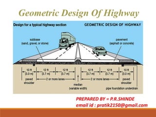
- 1. Geometric Design Of Highway PREPARED BY = P.R.SHINDE email id : pratik2150@gmail.com
- 2. Introduction: • The geometric design of roads is the branch of highway engineering concerned with the positioning of the physical elements of the roadway according to standards and constraints. The basic objectives in geometric designs are to optimize efficiency and safety while minimizing cost and environmental damage.
- 5. 5 ELEMENTS OF ROADS 1. Width of Pavement or Carriageway: It is total width of road on which vehicles are allowed to move. The width of pavement depends on width of traffic lane and number of lanes. Width of lane is decided based on maximum width of heavy commercial vehicle (HCV) which is legally permitted to use the roadway.
- 6. 6
- 7. 7
- 8. 8
- 9. 9 •The width of carriageway for various classes of roads standardised by Indian Roads Congress (IRC) are given below: Class Of Road Width Of Carriageway (m) Single lane road 3.75 Two lanes, without raised kerbs 7 Two lanes, with raised kerbs 7.5 Intermediate Carriageway 5.5 Multi-lane pavements 3.5 per lane
- 10. 10 2. Width of Formation or Roadway: Width of formation or roadway is the sum of widths of pavement or carriageway including separators, if any and the shoulders.
- 11. 11 Sr. No Road Classification Roadway Width (m) Plain and rolling terrain Mountainous and steep terrain 1 National & State Highways a) Single Lane b) Two lane 12 6.25 12 8.80 2 Major District Roads a) Single Lane b) Two lane 9 4.75 9 - 3 Other District Roads a) Single Lane b) Two lane 7.5 4.75 9 - 4 Village Roads ,Single Lane 7.5 4 Width of roadway are standardized by the Indian Roads Congress.
- 12. 3. Right of way:- • Right of way is the area of land acquired for the road, along its alignment. It is the distance between the boundary stones on either side of the road. RoW is the area of the road acquired for carriages way + other necessities + future extension, along its alignment. 4. Road shoulders:- • Shoulders are provided along the road edge to serve as emergency lane for vehicles. As per IRC, the minimum width of shoulders should be 2.5m. Road shoulders
- 13. 5. Side slope:- The slope of earthwork in filling or in cutting is called Side slope. It imparts stability to the earthwork. Typeof soil Slope Ordinary soil 1:1 to 1:1/2 Broken Rock 1:1/2 to 1:1/4 Soft Rock 1:1/4 to 1:1/8 Hard Rock Approx. Perpendicular
- 14. 6.Berm:- • The distance between the roadtoe and the inner edge of borrow pit is called berm. • It prevents the erosion of embankment soil. 7. Boundary stone :- • To indicate the boundary of land acquired for road, stones are driven in to the ground at about 30m distance on either side from the center line of the road. These stones are known as boundary stone.
- 15. 8. Side drain:- • For the drainage of rainwater, drains are provided on either side of the road. Normally, side drains are required for the road in cutting. For road in embankment, side drain is not necessary. 9. Building line:- • The distance from the center line of road on either side, within which construction of buildings is not permitted is called Building line. Side drain
- 16. 10.Control line:- • At the locations like bank, hospital, factory, theatre, etc. on the road, where more people gather disturbance to the traffic will be more. 11.Spoil bank:- • The banks constructed from surplus excavated earth on the side of road cutting parallel to its alignment, are known as Spoil banks. • The soil from spoil bank can be used for the repair of shoulders.
- 17. 12.Borrow pits:- •The pits dug along the road alignment for using excavated earth in the construction of embankment, are known as borrow pits. •The small portion of earth left undug in a borrow pit to measure depth of excavation is known as deadman.
- 18. 18 13. KERBS : • Kerbs indicates the boundary between the pavement and median or foot path or shoulder. • Kerbs may be mainly divided into three groups based on their functions- 1. Low kerb 2. Semi-barrier type kerb 3. Barrier type kerb
- 19. 1. Low or mountable kerbs : This type of kerbs are provided such that they encourage the traffic to remain in the through traffic lanes and also allow the driver to enter the shoulder area with little difficulty. The height of this kerb is about 10 cm above the pavement edge with a slope which allows the vehicle to climb easily. This is usually provided at medians and channelization schemes and also helps in longitudinal drainage. 2. Semi-barrier type kerbs : When the pedestrian traffic is high, these kerbs are provided. Their height is 15 cm above the pavement edge. This type of kerb prevents encroachment of parking vehicles, but at acute emergency it is possible to drive over this kerb with some difficulty. 3. Barrier type kerbs : They are designed to discourage vehicles from leaving the pavement. They are provided when there is considerable amount of pedestrian traffic. They are placed at a height of 20 cm above the pavement edge with a steep batter.
- 20. 20 Kerb Kerb
- 21. 14. Road Formation The Road Formation is the surface of finished earthworks on which a road pavement is constructed. It includes the earthworks, the general shaping of the road and basic drainage, but excluding storm water infrastructure.
- 22. 22 15. Cross slope or camber: Cross slope or camber is the slope provided to the road surface in the transverse direction to drain off the rain water from the road surface. Drainage and disposal of water from pavement is considered important because of the following reason: • To maintain stability, surface condition and increase life of pavement. • Topreventstrippingofbitumenfromaggregates. • Topreventslippingofvehiclesrunningathigh speed. • Therateofcamberorcrossslopeisusually designatedby1innor mayalsobeexpressedasa percentage. • The required camber of a pavement depends on type of pavementsurfaceandamountofrainfall.
- 23. The values of camber recommended by IRC for different types of road surfaces are given below: Sr.No Type Of Road Surface Range of camber in areas of Heavy rainfall Low rainfall 1 Cement concrete and thick bituminous surface 1 in 50 or 2 % 1 in 60 or 1.7 % 2 Thin bituminous surface 1 in 40 or 2.5% 1 in 50 or 2 % 3 Water bound macadam and gravel pavement 1 in 33 or 3% 1 in 40 or 2.5 % 4 Earth road 1 in 25 or 4% 1 in 33 or 3 % 14
- 24. Shape Of Cross Slope Or Camber (Types) 24
- 26. 16. Road Margins Road margins are the various cross sectional elements of the road except the carriageway or pavement width. Various road margins are shoulders, foot-paths, cycle-tracks, frontage paths, driveways, lay byes, side slopes and guide rails. • Shoulders: Shoulders are the parts of the formation width except carriage ways. In other words, shoulder is the part of the pavement which is non-surfaced. • They are used by the vehicular traffic as the emergency lanes or sometimes as the service lanes for the repairing of the non- expected problems. IRC recommends a minimum value 2.5 m for the shoulders for two lane rural roads. A width of 4.6 m is recommended so that a truck can be accommodated without interfering with the adjacent lane.
- 27. •Footpaths: Foot paths or pedestrian paths are the smoothly paved paths used by the pedestrians to walk parallel to the pavements. Footpaths are smoothly surfaced in order to attract the pedestrians to walk over them. Footpaths are necessary where the pedestrian traffic is considerable. •Cycle-tracks: Cycle tracks are provided to carry the cyclists. They are generally provided in the urban roads where the design speed is very high and it becomes necessary to separate the high speed traffic from the low speed traffic. Minimum of 2 m width is recommended for single lane and 1 m is added for constructing the extra lanes of the cycle tracks. •Frontage Paths: They are provided in front of the commercial buildings where it becomes a necessity. In urban areas they are provided with the dividers to separate from the vehicular lanes.
- 28. •Drive-ways: Drive ways are provided to reach the buildings like fuel pumps or service centres. Drive ways should have a less width as much as possible because they are hindrance to the pedestrian traffic travelling along the foot-paths. •Parking Lanes: They are provided for parking the vehicular traffic generally needed in the market centers or the urban areas. Parallel parking is recommended in order to avoid the hindrance to the traffic and a minimum of 3 m parking lane is recommended. •Side Slopes: A proper, flatter/gentle side slopes are necessary in case of filling or cutting for the stability of the pavements. If possible they must be provided with the landscaping so making them a pleasant and aesthetic appearance and making more stable.
- 29. • Guide Rails: Guide rails are provided on the roads on filling generally on the hills, on the outer edges, for the psychological as well as physical protection to the driver. • Lay Byes: Lay Byes are the paved areas provided at some places on the sides of the lanes for providing a stoppage for the vehicles.
- 30. 17. Median or Traffic Separator: 30 Median is provided between two sets of traffic lanes intended to divide the traffic moving in opposite directions. The main function of the median is to prevent head-on collision between vehicles moving in opposite directions on adjacent lanes. The traffic separators used may be in form of pavement markings, physical dividers or area separators.
- 31. 31
- 32. 32 •The width of medians for roads standardised by Indian Roads Congress (IRC) are given below: Sr.No Type Of Road Width Of Medians (m) Desirable Minimum 1 Expressway 15 10 2 Other Highways 5 3 3 At intersection of urban roads 5 1.2 4 On Long Bridges 1.5 1.2
- 33. 33
- 34. 34 Design speed •The design speed is the main factor on which geometric design elements depends. Design speed is a selected speed used to determine the various geometric features of the roadway. The sight distance, radius of horizontal curve, superelevation, extra widening of pavement, length of horizontal transition curve and the length of summit and valley curve are all depends on design speed. Factors affecting design speed The road's functional classification (class of road) Terrain The speed standards of a particular class of road thus depends on the classification of the terrain through which it passes. The terrain have been classified as plain, rolling, mountainous and steep, depending on the cross slope of a country as given below.
- 35. Classification of Terrain 35 Terrain Classification Cross Slope Of Country in % Plain 0-10 Rolling 10-25 Mountainous 25-60 Steep Greater than 60
- 36. 36 Design Speed On highways The design speed (ruling & minimum) standardized by the IRC for different classes of roads on different terrains in rural areas are given below.
- 37. 37 Gradients: Gradient is the rate of rise or fall along the length of road with respect to the horizontal. It is expressed as a ratio of 1 in n or also as percentage such as n%. Types Of Gradients: Ruling gradient Limiting gradient Exceptional gradient Minimum gradient ‘
- 38. 38 Ruling gradient: • Ruling gradient is the maximum gradient within which the designer attempts to design the vertical profile of a road. Ruling gradient is also known as ‘Design gradient’. • For selection of ruling gradient factors such as type of terrain, length of the grade, speed, pulling power of vehicle etc. are considered. In flatter terrain, it may be possible to provide at gradients, but in hilly terrain it is not economical and sometimes not possible also Limiting gradient: • This gradient is adopted when the ruling gradient results in enormous increase in cost of construction. On rolling terrain and hilly terrain it may be frequently necessary to adopt limiting gradient. ‘
- 39. 39 Exceptional gradient: • Exceptional gradient are very steeper gradients given at unavoidable situations. • They should be limited for short stretches not exceeding about 100 m at a stretch. Minimum gradient: • This is important only at locations where surface drainage is important. Camber will take care of the lateral drainage. • But the longitudinal drainage along the side drains require some slope for smooth flow of water. Therefore minimum gradient is provided for drainage purpose and it depends on the rain fall, type of soil and other site conditions. • A minimum of 1 in 500 may be sufficient for concrete drain and 1 in 200 for open soil drains are found to give satisfactory performance..
- 40. 40 ‘ Type of terrain Ruling gradient Limiting gradient Exceptional gradient Plain and rolling 3.3 % 1 in 30 5% 1 in20 6.7 % 1 in 15 Mountainous and steep having elevation more than 3000 m above MSL 5% 1 in20 6 % 1 in 16.7 7 % 1 in 14.3 Mountainous and steep having elevation more than 3000 m above MSL 6 % 1 in 16.7 7 % 1 in 14.3 8 % 1 in 12.5
- 41. SIGHT DISTANCE: • The actual distance that is observed along the road surface which is visible for a driver from a specified height above the carriage way is called as the sight distance at a point. This distance will let the driver see all the stationary and the moving objects in front of the vehicle. • Mainly in the geometric design of road construction, mainly three sight distances are taken into consideration. They are: SSD – Stopping Sight Distance or Absolute Minimum Sight Distance ISD – Intermediate Sight Distance: This is twice the value of SSD OSD – Overtaking Sight Distance.
- 42. Stopping Sight Distance: • This is defined as the sight distance that is available for the moving the vehicle in the highway that will enable the driver to stop the vehicle safely without collision with any other obstacle.
- 43. The sight distance available on a road to a driver at any instance depends on : 1. Features of the road ahead. 2. Height of the driver’s eye above the road surface. 3. Height of the object above the road surface. The distance within which a motor vehicle can be stopped depends upon the factors listed below: 1. Total reaction time of the driver. 2. Speed of vehicle 3. Efficiency of breaks 4. Frictional resistance between the road and the tyres. 5. Gradient of the road.
- 44. 44 Overtaking Sight Distance: • The minimum distance available for the driver to safely overtake the slow vehicle in front of him by considering the traffic in the opposite direction is called as the overtaking sight distance or safe passing sight distance available. • This distance will make us see whether the road is clear to undergo an overtaking movement. Factors on which overtaking sight distance affects Spacing Between the vehicles. Speed of the vehicles. The gradient of the road. The acceleration rate of the overtaking vehicle. The velocities of the vehicle which is overtaking, overtaken and that coming in the opposite direction. The driver skill. The reaction of the driver.
- 45. Intermediate sight distance: • This is defined as twice the stopping sight distance. When overtaking sight distance can not be provided, intermediate sight distance is provided togive limited overtaking opportunities to fast vehicles.
- 46. Curve • A curve is nothing but an arc which connects two straight lines which are separated by some angle called deflection angle. • This situation occurs where the alignment of a road way changes its direction because of unavoidable objects or conditions. • The object may be a hill or a lake or a temple etc. so, for the ease of movement of vehicle at this point a curve is provided. Necessity of curves • Try to avoid a large obstacle. • To reduce the steepness, or grade, of the roadway on a hill.
- 47. Types of Curves in Alignment of Highways In general, there are two types of curves and they are • Horizontal curves • Vertical curves Horizontal Curves: • The curve provided in the horizontal plane of earth is called as horizontal curve. It connects two straight lines which are in same level but having different directions. Horizontal curves are of different types as follows: 1. Simple circular curve 2. Compound curve 3. Reverse curve 4. Transition curve 5. Spiral 6. Lemniscate
- 48. 1. Simple Circular Curve: • Simple circular curve is normal horizontal curve which connect two straight lines with constant radius. 2. Compound Curve: • Compound curve is a combination of two or more simple circular curves with different radii. In this case both or all the curves lie on the same side of the common tangent.
- 49. 3. Reverse Curve • Reverse curve is formed when two simple circular curves bending in opposite directions are meet at a point. This points is called as point of reverse curvature. • The centre of both the curves lie on the opposite sides of the common tangent. • The radii of both the curves may be same or different.
- 50. 4. Transition Curve • A curve of variable radius is termed as transition curve. It is generally provided on the sides of circular curve or between the tangent of circular curve. Its radius varies from infinity to a certain fixed value. • Transition curve helps gradual introduction of centrifugal force by gradual super elevation which provides comfort for the passengers in the vehicle without sudden jerking.
- 51. 5. Spiral Curve • Spiral is a type of transition curve which is recommended by IRC as ideal transition curve because of its smooth introduction of centrifugal acceleration. It is also known as clothoid.
- 52. 6. Lemniscate curve • Lemniscate is a type of transition curve which is used when the deflection angle is very large. In lemniscate the radius of curve is more if the length of chord is less.
- 53. Vertical Curves The curves provided in vertical plane of earth is called as vertical curve. This type of curves are provided when the ground is non-uniform or contains different levels at different points. vertical curves are divided into two types 1. Valley curve 2. Summit curve
- 54. 1. Valley Curve: • Valley curve connects falling gradient with rising gradient so, in this case convexity of curve is generally downwards. It is also called as sag curve.
- 55. 2. Summit Curve • Summit curve connects rising gradient with falling gradient hence, the curve has its convexity upwards. It is also called as crest curve.
- 56. WIDENING OF ROADS • On horizontal curves , especially when they are not of very large radius, it is a common practice to widen the pavement slightly more than the normal width, the object of providing Extra Widening of pavements on horizontal curves are due to the following reasons.... (a) An automobile such as car, bus or truck has a rigid wheel base and only the front wheels can be turned. When the vehicle takes a turn to negotiate a horizontal curve, the rear wheels do not follow the same path as that of the front wheels. This phenomenon is called ‘off tracking’. The off tracking depends on the length of the wheel base of the vehicle the turning angle or the radius of the horizontal curves.
- 57. (b)At more than design speed if super elevation and lateral friction jointly cannot counteract the centrifugal force, full outward slipping of rear wheels may occur and thus more width of road is covered. This condition occurs at very high speeds. (c)At start of the curves drivers have a tendency to follow outer edge of the pavement to have better visibility and large radius curved path. This also necessitates extra width of the road. (d)While overtaking operations on horizontal curves driver will need more spacing from the other vehicles to feel safer.
- 58. Analysis of extra widening on horizontal curves The extra widening of pavement on horizontal curves is divided in to two parts (i) Mechanical widening and (ii) Psychological widening. I) Mechanical widening :- • The widening required to account for the off tracking due to the rigidity of wheel base is called Mechanical widening . Formula of calculating mechanical widening is W = Nl2__ 2R Here, n =number of traffic lanes l = length of wheel base of longest vehicle in m R= radius of horizontal curves in m
- 59. II) Psychological widening :- At horizontal curves drivers have a tendency to maintain a greater clearance between the vehicles than on straight stretches of road. Therefore an extra width of pavement is provided for psychological reasons for greater manoeuvrability of steering at higher speeds and to allow for the extra space requirements for the overhangs of vehicles. Psychological widening is therefore important in pavements with more than one lane. An empirical formula has been recommended by IRC for deciding the additional psychological widening Wps which is dependent on the design speed, V of the vehicle and the radius. R of the curve. The psychological widening is given by the formula: Wps
- 60. Hence the total widening We required on a horizontal curve is given by: We= Wm + Wps + Here, n =number of traffic lanes l = length of wheel base of longest vehicle in m R= radius of horizontal curves in m V= design speed Kmph W = __ 2R Nl2
- 61. The extra width recommended by the Indian Road Congress for single and two lane pavements are given in table:
- 62. Super elevation (e) 62 • In order to counteract the effect of centrifugal force and to reduce the tendency of the vehicle to overturn or skid, the outer edge of the pavement is raised with respect to the inner edge, thus providing transverse slope through out the horizontal curve. This transverse inclination of pavement surface is known as super elevation or cant or banking. The Super elevation ‘e’ is expressed as the ratio of the height of outer edge with respect to the horizontal width.
- 63. The general equation for the design of super elevation is given by, e + f = v²∕gR Where, e = rate of Super elevation in % V = velocity of vehicle in m/s f = lateral friction factor = 0.15 g = acceleration due to gravity = 9.81 m/s2 R = radius of circular curve in meters. If velocity is in KMPH then e + f = V2/ 127R 63
- 64. 64 Maximum Super elevation • as per above equation the value of super elevation needed increases with increase in speed and with decrease in radius of the curve, for a constant value of coefficient of lateral friction f. In a highway, with mixed traffic, the value of super elevation so obtained from equations is to be limited to avoid the danger of overturning. This maximum allowable limit of super elevation is called maximum super elevation. • Indian Roads Congress (IRC) had fixed the maximum limit of Super elevation in plan and rolling terrains and in snow bound areas as 7.0 %. • On hill roads not bound by snow a maximum Superelevation upto10% is recommended. • On urban road stretches with frequent intersections, it may be necessary to limit the maximum Superelevation to 4.0 %.
- 65. 65 Minimum Superelevation • If the value of super elevation obtained from the equations is equal or less than the usual camber value provided to the road surface then it should be equal to the camber slope. This lower limit of super elevation equal to the amount of camber is termed as minimum super elevation. It is (2-4) % for drainage purposes, especially for large radius horizontal curve
- 66. Method Of Providing Super elevation Introduction of super elevation on a horizontal curve of a road is an important feature in road construction. Super elevation is provided in the following two methods. 1.Elimination of the crown of the cambered section. 2.Rotation of pavement to attain full super elevation. 1. Elimination of The Crown of The Cambered Section • In this method, the outer half of the camber is gradually decreased. • This may be done by two methods.
- 67. • In the first method, the outer half of the camber is rotated about the crown at the desired rate such that the surface falls on the same plane as the inner half.
- 68. • In the second method, the crown is progressively shifted outwards. This method is not usually adopted.
- 69. 2. Rotation of Pavement To Attain Full Superelevation • In this stage, super elevation is gradually provided over the full width of the carriageway so that the required super elevation is available at the beginning of the circular curve. • The different method employed for attaining the super elevation is as follows:
- 70. A. Revolving Pavement About The Centre Line • In this method the surface of the road is rotated about the centre line of the carriageway, gradually lowering the inner edge and rising the upper edge. The level of the centre line is kept constant. This method is widely used.
- 71. B. Revolving Pavement About The Inner Edge • In this method, the surface of the road is rotated about the inner edge, raising the centre and outer edge. C. Revolving Pavement About The Outer Edge In this method, the surface of the road is rotated about the outer edge depressing the centre and inner edge.
- 72. CROSS SECTION OF NATIOAL HIGHWAY IN EMBANKMENT
- 73. CROSS SECTION OF NATIOAL HIGHWAY IN CUTTING
- 74. THANK YOU