Weitere ähnliche Inhalte
Ähnlich wie Introduction to partial discharge
Ähnlich wie Introduction to partial discharge (20)
Introduction to partial discharge
- 1. © Partial Discharge UK 2015
www.partialdischarge.co.uk
What is partial discharge?
The insulation in high voltage (HV) systems is constantly ageing from thermal and mechanical
stresses. It is subject to detrimental external influences such as heat, humidity, chemical and
other contaminating agents. Additionally, insulation can contain defects imparted during its
manufacture that will not become apparent until it is in service. Incorrectly installed cables,
terminations, joints and switchgear can further compound these issues.
Predicting the life of HV insulation is very difficult as many of the factors above are impossible
to predict and their effects vary from one installation to another. Destructive techniques that
require sampling and analysis require plant to be shutdown and can only be done
infrequently. Therefore, non-destructive methods of determining the insulation quality are
highly desirable, especially in today’s industrial environment where plant shutdowns are
minimised or don’t happen at all!
As HV insulation fails, localised electrical discharges occur that only partially bridge the
insulation in gas filled voids in the bulk of the insulating material, in air on the surface, or at
protrusions whose raised profiles intensify the electrostatic field. These localised discharges
are known as Partial Discharges (PD). PD can persist for many years, or in some cases
rapidly escalate, until catastrophic failure occurs. Fortunately, detection of PD can be
accomplished using a variety of non-destructive methods without the need to shutdown plant.
PD detection and monitoring is therefore a diagnostic tool that gives a prognosis of insulation
condition. Detecting PD levels over time will indicate and pre-warn of the failure of the
insulation in HV cables, switchgear, terminations, joints, transformers, motors and generators.
Leading research indicates that over 85% of all failures in HV equipment are due to
partial discharge. Early detection and monitoring therefore prevents major events and
their implications for personnel safety.
Because of the high field strengths required to break down air, PD detection is only suitable
for HV equipment operating at voltages greater than 3.3kV.
Effects of PD
PD pulses have a distinct characteristic. Generally, they have a steep rise time (1-2nS) and
short duration in the order of 5nS, combined with typical amplitude of 1V. In AC systems, they
occur on the positive and negative rising quarter-cycles. Due their short and spiky nature, PD
pulses contain high frequency components of several hundred MHz, and are usually
accompanied by other energy releases, as summarised below.
• Electromagnetic radiation in 300-2000MHz range
• Ultrasonic radiation
• Audible, heard as a fizzy sound
• Localised heat at the source of the PD
• Ultra-violet and visible corona
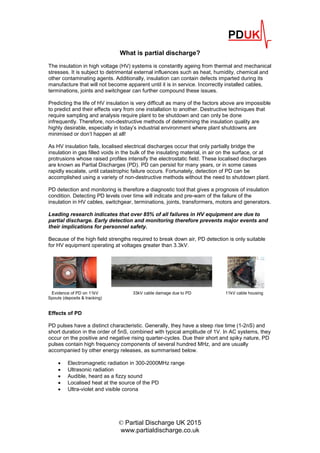
33kV cable damage due to PDEvidence of PD on 11kV
Spouts (deposits & tracking)
11kV cable housing
- 2. © Partial Discharge UK 2015
www.partialdischarge.co.uk
PD causes chemical changes in the insulating medium. This fact enables PD, as well as other
failure modes, to be detected in the insulating oil of transformers and switchgear.
Detecting PD
PD detection can be accomplished by sensing the various energy releases as outlined above.
These methods are detailed below.
Energy type Sensing technique
Electromagnetic Transient Earth Voltage & UHF reception
Acoustic 20kHz ultrasonic & audio microphones
Thermal Thermal imaging, hot-spot measurements
Light Optical & Ultra-violet
Direct electrical methods using high frequency coupling capacitors and current transformers
can also be used. These are employed in motors and generators as outlined in IEC60270.
Dissolved gas analysis (DGA) of insulating oils can identify a multitude of potential issues in
transformers and switchgear.
In practice more than one sensing technique will be employed. This is mainly to distinguish
between true PD activity and other electrical noise in the vicinity.
A brief description of each sensing method follows.
Electromagnetic
PD activity is accompanied by electromagnetic (radio) waves that propagate from the PD site.
These waves induce minute currents in the metal enclosure. Due the high frequency of the
pulses, the impedance of the earthed metal is substantial enough to create small voltages.
These were discovered in the 1980’s are known as Transient Earth Voltages (TEV). Detection
is by the contact of a capacitive probe to the surface of the metal in the form of a handheld
detector. TEV is an established method for detecting PD within the insulating medium.
PD derived electromagnetic energy can be in excess of 1GHz, although the majority is around
200MHz. This energy is detectable using UHF equipment. Multiple antennas enable time-of-
flight techniques to locate the source of PD.
Acoustic
Both in the audible and ultrasonic ranges. PD activity on the surface of an insulator causes
rapid expansion of the nearby air and a consequent pressure wave is generated. Audible as a
fizzing sound (rather like bacon frying in fat), and in the 20kHz ultrasonic range. Detection is
via a sensitive microphone tuned to 20kHz and converted to audio heard in a set of
headphones. This is a useful technique when gaps in the enclosure allow the sound energy to
escape. It should be noted that due the complex propagation path, the sound level does not
easily relate to the magnitude of the PD. The energy will rebound and attenuate inside the
enclosure. Ultrasonic microphones on long leads with flexible goose necks enable detection
in difficult locations.
Thermal
PD causes hot spots due to the high current density at the PD site. Irregular surfaces due to
poor installation, contamination or manufacturing defects can lead to lumps and bumps on the
insulation. Detection using thermal imaging is possible. However, as most HV gear is metal
clad access to the hot spot is difficult and in any case the thermal effect is small in
comparison to the overall heat generated. For these reasons, thermal imaging is not practical
in most cases.
- 3. © Partial Discharge UK 2015
www.partialdischarge.co.uk
Optical methods
PD excites photons due to the ionisation and recombination processes during the discharge
event. The light intensity depends mainly on the magnitude of the discharge and the
insulation medium. The spectrum can be from visible light through ultra-violet to infra-red. PD
in air is dominated by the abundance of nitrogen. Consequently, 90% of optical energy
generated is in the ultra-violet region with some in the visible range in total darkness. Of
course one needs line of sight with the PD site in order for detection.
Surveying for partial discharges in HV equipment
A regular testing schedule of HV assets provides predictive
data on the condition of the insulation.
PDUK uses a variety of techniques to detect PD in switchgear,
cables, transformers and machines. From initial detection we
locate the source and, if necessary, install monitoring
equipment to establish the trend of the PD levels.
A comprehensive report is provided detailing the PD levels. We use a traffic light system to
show any assets requiring attention.
Contact us to discuss your PD survey requirements
info@partialdischarge.co.uk
www.partialdischarge.co.uk