SlideShare ist ein Scribd-Unternehmen logo
1 von 24
Downloaden Sie, um offline zu lesen
Tips on Designing Cost Effective
Machined Parts
By Joe Osborn, Founder, OMW Corporation (www.omwcorp.com, a cnc machine shop), and Adjunct Faculty
Member in Metals Technology at the College of Marin. Copyright(c)2006. All rights reserved. Illustrations by the
author except as noted.
(Please note: Feedback is welcome and appreciated! Email Joe Osborn directly at jhko@aol.com)
For a .PDF version of this e-booklet, click here.
CONTENTS
I.) DRAWINGS AND PRINTS
II.) DESIGNING FOR MACHINING
III.) SAVING MONEY IN SETUPS AND FIXTURING
IV.) RAPID PROTOTYPING, STEREOLITHOGRAPHY, FDM, ETC.
V.) OTHER WAYS TO SAVE MONEY ON MACHINED PARTS
VI.) DESIGNERS CHECKLIST
VII.) OTHER RESOURCES
Over the years at OMW, we've made thousands of parts for hundreds of customers and learned a great
deal about how to make parts less costly. Sometimes very small changes in design can generate large
savings in part costs. Understanding good part design as it applies to machined parts, and
understanding the assumptions machine shops make when you send them a print will help you to save
money, avoid costly mistakes, and get parts that work well and exceed your expectations!
I.) DRAWINGS AND PRINTS
Good parts start with good prints
We pay attention to what you say and don't say. We have to sell parts!
If you want the most cost effective part, it's important to spend some time on your drawing.
Machinists tend to think visually. Remember that your print is the primary communications device
between you and the machinist working on your part. What you want to see in your parts needs to be
clearly communicated in your drawings. You don't have to be a professional draftsman to create a
good drawing; we've seen excellent drawings hand sketched on a piece of copier paper. Just make
sure that it is clear and contains the very basics of legibility (you'd be surprised how many prints
don't!):
Text should be large enough to read easily
Lines should be dark and legible
Avoid light grey or blue tones or other colors that don't copy or fax well
Don't use yellow as a color, it's hard to read
Illustration- Here's a perfectly readable print. Note the careful dimensions with appropriate
tolerancing, the use of notes, revision history, material and finish specification, etc. The note
on who to contact with questions should be a mandatory feature in any drawing!
Illustration- A poor print. Hastily done, poor default dimensioning, bad color choices, critical
features not called out, etc. You'd be amazed how many prints from professional engineers
we receive that look like this. Any time saved in this drawing will be lost three-fold in the
phone calls required for clarification and the likely re-do of an incorrect first part. Many shops
will not bid on the job when they receive a print like this.
Illustration- A reasonable hand-drawn print. Though this print was done via a quick pencil
sketch, the result is perfectly usable. Simple parts don't require a fancy CAD drawing, but
they do require some attention and clear communication of details.
Give parts unique names and part numbers
When providing prints for multiple parts, use unique part numbers and clear names to identify
different parts. It is amazing how often this is not done. Avoid using similar names that are easily
confused.
Specify the material you want
We get many prints for parts where the material for the part is not specified. This usually results in a
call or email back to the customer and a delay in the turn-around for the quote. If you need a very
specific material, for example a specific grade of stainless or aluminum, be sure to specify it (e.g., AL
6061-T651, SS 304L). If you just specify a general material, e.g., "stainless steel", that's fine, but be
aware we will usually select the least expensive and easiest to machine grade (in stainless, 303; in AL,
6061).
Be specific with material finishes
If you have a particular surface requirement, be sure to put it in the print (e.g., 32 finish, etc.). If you
desire a specific portion of the part to be ground, turned or milled, specify that as well. Don't assume a
round part will be turned, often the part will be done on the CNC mill rather than the lathe. Generally
it is cheaper to let the shop decide the approach to take, so unless you have a specific reason it is
better to leave the machining process choice up to the shop.
It is important to note that most shops have a certain standard for part finishes that you can expect,
whether you specify finishes or not. It's important to understand how the shop views finishing.
Most shops, including OMW, have found that nice looking parts are easier to sell than poor looking
parts, even when both sets of parts are fully within tolerance. Because of this, shops usually try to
maintain a consistent surface finish- sanding, shaking, and tumbling (vibratory deburring) parts is
common. These techniques remove most tool marks and make the parts look nicer. In addition, sharp
edges are smoothed and parts are easier to handle. Shops will also usually break sharp edges on parts
and holes will be lightly chamfered and edged deburred, whether the parts are tumbled or not. Note
that a machine shop is not a jeweler, so you will generally still see some small non-critical scratches.
If for a specific reason you need a sharp edge on your part, be sure to specify it in the print, otherwise
you can be pretty sure it will be deburred and chamfered as a matter of course by the shop. And if you
don't want your parts tumbled or sanded, be sure to specify this. Note pricing may increase since
tumbling often reduces hand deburring.
Illustration- If you look closely at this part, you'll notice chamfered edges, the tops of holes
deburred with a light countersink, and machined surfaces lightly buffed to improve the
appearance. These are typical "standard practice" finishing details often added by machine
shops. Note that none of these features are on the part print. If you want something done
differently (a sharp edge, for example), be sure to call it out on the print.
Tell us what the part is for and how it is used.
It almost always helps the machinist to know what a part is for and how it is being used. Doing
custom machining is like a game. You are continually trying to figure out exactly what your customer
wants. You win when a finished part works well and your customer is happy with it. Knowing how a
part works and what it is for helps tremendously in this regard.
When possible, use solid modeling to create complex part design
Using a modern solid modeling CAD system (such as Solidworks, Pro Engineer or Inventor) can help,
especially if parts have complex 3D surfaces or features that are difficult to see in a 2D drawing. In
addition, we program directly off the outside surfaces when doing 3D machining of many parts. In
this case, having a solid model can save a huge amount of time any money since we don't have to
recreate the model ourselves from the 2D information.
Illustration- Can you tell what is going on with this part based on the 2D drawing views?
Illustration- With this 3D model, the part geometry becomes instantly obvious. Complex
curved shapes also lend themselves well to 3D modeling.
Provide a dimensioned or semi-dimensioned 2D print, even when using solid modeling
There is a trend among engineers to provide only a solid model to a machine shop. This is an attempt
to save time, since in some CAD systems, like Solidworks, information on holes and other attributes
can be shown in the design tree of the solid model. If the machine shop has a license for the software
in-house, they can refer to the design tree and theoretically machine the part without any detailed 2D
drawing or print at all.
While this sounds good, in practice it doesn't work very well. A sheet of paper is still much more
convenient than a computer, even a laptop. You'd be amazed how a paper drawing is carried around
the shop and referred to as the job moves from machine to machine. When at all possible, supply a
detailed print with the solid file.
Note that for complex parts, sometimes you don't need to fully detail the print. Some features,
especially complex 3D surfaces and organic surfaces are very difficult to dimension in a 2D drawing.
Since we program the tool paths directly off the part geometry anyway, we really only need major
dimensions, critical dimensions with tolerances, notes on features, etc., in our detailed print.
When designing on the computer, make sure part geometry in your CAD files match the
dimensions shown in the corresponding drawings.
Don't design a part "visually", and then add dimensions that have little or no connection with the
computer geometry. If we get a computer file, unless we are specifically warned to the contrary, we
always assume the part geometry is dimensionally correct. Always assume the machinist will be
programming off the computer part geometry. Avoid the urge to update a dimension in your drawing
while expecting to update the solid model "later on".
Obviously, with hand-made drawings, the dimensions take precedence.
Use the drawing title block to advantage
Fill out the items in the drawing title block, including Material, tolerancing and finishes. Use the
revision blocks if changes are being made.
Illustration- Here's a decent title block, with a good deal of useful information provided. Avoid
the temptation to use the CAD system defaults. A few minutes adding real information will
pay dividends later on.
Pay attention to tolerancing, we do!
Pay attention to how many decimal places you use when calling out a dimension. It is amazing how
many drawings we get where the title block clearly specifies tolerancing based on the number of digits
shown after the decimal point (e.g., .00=+-.010" , .000= +-.002), but the person creating the drawing
just uses the default number of decimal places (usually three or four places). This means every
dimension shown appears to require the highest precision! The machinist can't afford to have a part
rejected, so without the proper information he or she will attempt to make every dimension on the part
to the specified tolerance. Obviously this will create a VERY expensive part. Be sure to spec high
tolerances only where you truly need them.
The same thing applies to thread call-outs. Don't put a thread tolerance (e.g., H3) unless you really
mean it and intend to check it. In my many years of machining, I can only think of a handful of cases
where a specific thread tolerance was really justified. In most all cases, just "8-32" is enough said. (If
the tolerance is not specified, we use the most common tolerance taps).
Illustration- One of the most common mistakes is leaving the default CAD dimension
precision set, as is shown here. This will end up being a very expensive part, since without
other information the machine shop will attempt to hold high tolerances on every feature.
Don't fall into this trap!
Dimension consistently from the same edges or datum point
Dimension your part's features from a single point or datum (eg, the intersection of two easy-to-locate
outside edges on a square part, or the center of a large hole). Don't, for example, dimension one
feature from the left edge, and another from the right edge willy nilly. This can lead to tolerance
"build-up" and is generally bad practice. Remember, a machinist will usually be picking up two edges
of a part (or the center of a hole) to set the X,Y zero of his machine. All features in that setup will be
machined from on this same zero location. Dimension your print the same way.
Don't specify the tap drill size on the print
Many modern CAD systems have an easy default hole wizard which automatically inserts the tap drill
size for the tapped hole drawn. Avoid using this unless you know exactly what you are doing. Just
specify the thread desired. It is much better in most cases to let the machinist decide the tap drill size
and whether the hole will be roll or cut tapped, or even threadmilled. Many factors can affect this
choice, including the type of tap and material, the material hardness, the temper, the size and depth of
the hole, etc. For example, roll tapping is much more cost effective for small holes in 6061 aluminum
when rigid tapping on a CNC machine. If you specify a tap drill size on the print, you may force the
machinist to choose between a more expensive and less consistent way to make your thread, or
ignoring your note altogether. It's likely he or she will call you and waste both your time and money.
Unless it really matters, leave the tap drill specification up the machinist.
II.) DESIGNING FOR MACHINING
Designing parts that are easy to machine can make a huge difference in part cost and quality.
Make sure inside corners take into account endmill radii.
Try not to design sharp, square inside corners. Allow for the radius of the endmill. If you must have a
pocket with sharp square corners, there are ways to accomplish this task (broaching, EDM, etc.), but
they are usually much more expensive than simple milling.
Illustration- It is very easy to design square pockets such as the example on the left above,
but it is harder to machine them than you would think. An end mill will always leave rounded
inside corners, as shown in the right hand version. A smaller endmill can minimize the
radius, but it will still be there. Very square corners can be created through other techniques
(broaching, EDM, etc.), but this gets pricey.
If you are fitting something inside a pocket, often the corners can be cut away with an endmill so that
the sharp corners of the mating part will still fit without jeopardizing alignment.
Illustration- Often, pocket corners can be cut away so that a mating square part can still fit
accurately in the pocket.
Watch EM length to diameter.
Endmills work best when they are very rigid. Avoid making deep pockets or inside corners with small
radii. Generally, an endmill will cut easily with a length of up about 4 times its diameter (e.g., a �"
endmill cutting a pocket up to an inch deep). Endmills can be cut deeper, sometimes up to 10-15 times
the diameter, but this gets progressively harder and more time consuming to do. It these cases, the mill
must be "stepped down" the wall of the pocket in very small increments, or run at extremely slow rpm
and feed rates. In general it is best to limit pocket depth to as small a multiple of end mill diameter as
possible.
Illustration- A deep pocket with small inside corners cut with an extra long endmill is just
asking for trouble. Endmills like this will chatter and break easily, and surface finish will be
poor.
Illustration- One way to work around the above problem would be to build up the part from
three components. This way the pocket could be easily milled from the side and all corners
could be kept sharp.
Plan parts for standard EM sizes; make corners larger than EM diameter
As CNC milling has become more common, shops have tended to use standard size endmills for much
of the milling work. This is because modern CNC milling machines can mill arcs and curves without
regard to endmill diameter. Before CNC, on a manual mill, you would have to choose an endmill with
the diameter of the inside corner you wanted to mill, or use a difficult-to-setup rotary table. Now
nearly any radius can be milled with a standard size endmill. For efficient material removal shops still
need endmills of different sizes, but most shops keep a good supply of only the common sizes. These
are usually even fractions of an inch, e.g., 1/16", 3/32", 1/8", 3/16", 1/4", 1/2", 3/4", etc. Metric sizes
in even mm increments are common as well.
When designing parts, it is good practice to design inside corners with these endmills in mind.
However, when possible don't pick corner radii that are exactly the same as endmill diameters. The
reason is that if you bring a .25" diameter endmill into a corner of .25" for example, the endmill has a
large portion of its surface area in contact with the work during the finishing pass. This leaves the
endmill prone to chatter and poor surface finish. It's better to machine a .300" diameter corner with a
smaller endmill, such as a .250" diameter. If you need something close to a .25" diameter corner,
choose a slightly bigger radius instead, say .27 or .30. Avoid very small differences, as a .251 corner
will effectively machine the same as a .250 corner. You need to add .020 or .030" to lower the surface
area contact sufficiently.
Illustration- If the corner of the pocket is has the same radius as the endmill, there is a large
area of surface contact on the finishing pass (shown in red). Designing a slightly larger
corner than a standard endmill size limits the surface contact and reduces potential chatter.
Don't specify too deep tapped holes
Putting threads in holes (tapping) is usually not a difficult process. But it gets progressively more
difficult and expensive as the tapped holes get deeper. Keep in mind that for maximum strength, you
only need a hole to be tapped to a depth of 1 to at most 3 times the diameter. Any deeper and the
screw will break before the threads pull out. Think about the average commercial nut on a bolt. The
thickness of the nut is usually is only 1 to 1.5 times the bolt diameter, because this is all the thickness
that is needed. But despite this, we often see prints with tiny holes tapped to extreme depth.
Bear in mind too that the threaded portion of taps is not too long. A 4-40 tap, for example, only has
5/8th of an inch worth of threads on it. If a deeper threaded hole is specified, the tap shank has to be
ground back. Because of the depth of the hole there is also an extreme risk of breakage. A very
expensive hole to manufacture indeed!
If you need to have a long through hole to clear, for example, a threaded shaft, try to specify threads
on only one side of the hole, with a drilled hole from the other end.
Illustration- Long tapped holes (A.) require custom tooling and are expensive to make.
Instead, design shorter holes tapped from each side (B.). A through drilled hole, but with
short threads from each end is also acceptable (C.). If you need to pass a long fastener or
part through the threaded hole, consider back boring as shown in D.
Watch for High walls- EM, toolholder and spindle clearance issues
Another problem area in machining is tool, toolholder and spindle clearance, especially next to high
walls or other part features. The end of a standard ER-16 collet chuck, which is often used to hold
smaller endmills and drills, is about 1.125 inch in diameter. If you have a pocket next to a high wall,
for example, this clearance can present a problem. Sometimes a smaller chuck, like an ER-11, can be
used. But this will still have a diameter of about .75", and can only hold quite small tools up to about
.25".
You need to bear in mind these tooling clearance issues when designing parts. As always, there are
work-arounds, but they are expensive and time consuming.
When possible, design multiple parts or pieces that can be bolted, fit, or welded together to alleviate
clearance issues.
Illustration- The photo shown is a typical machine tool spindle with an endmill holder. The
accompanying illustration shows typical toldholder and spindle sizes. These numbers are
approximate and will vary with the specific machine tool, taper size (#30, #40, #50), etc., but
they give you an appreciation of types of clearances required for easy machining.
Limit Machining Risk Factors- Design simple parts
An important but little talked about factor in part cost is the risk involved in the work. For example, if
a shop is going to engrave text on a $20,000 mold cavity supplied by the customer, they will charge
many times more than if they are asked to engrave the same text on a $10 piece of steel. The reason is
risk. The shop cannot afford to make a mistake on the mold, so they will spend much more time
testing and proving out the procedures than on the cheap piece of steel. In addition, if they do make a
mistake (and mistakes are part of the business of machining) on a costly mold, it will mean a costly
insurance claim or worse. As such, the shop charges a premium.
The logic follows if a part gets too valuable. Imagine a part with hundreds of features fashioned out of
a huge block of aluminum. The single part might take days to make. If the shop makes a mistake near
the end of the project, the part may have to be scrapped at enormous cost. As a result, the shop will
charge a premium. If the same part where made of several smaller and less complex parts bolted
together, the project would cost less, even though the shop now had to produce a larger number of
parts.
As a rule of thumb, it is better to design assemblies out of simple, smaller parts than to try to make a
single large complex part.
Illustration- A complex part as shown might be better designed as three separate parts
fastened together with shoulder bolts or screws with locating pins. Each of the individual
parts then become less risky, clearance problems are avoided, and significant material is
saved as well. Often the three simpler parts will be much less expensive to manufacture than
a single more complex part.
III.) SAVING MONEY IN SETUPS AND FIXTURING
Workholding and fixturing is often one of the most expensive parts of the machining process. Besides
designing parts that are easy to machine, it is very important to design parts that are easy to hold.
Design for Vise fixturing (size limitations, etc.)
One of the most common and least expensive workholding devices in the shop is the Kurt brand
milling vise. The vise is a precision tool most commonly with jaws six inches wide, 1.75" deep and
capable of opening about 9 inches. This tool is ground flat and parallel to two ten-thousandths of an
inch, and is capable of both great precision and great speed in loading and unloading parts. However,
to make the simplest and cheapest use of a milling vise like this, parts need to have parallel edges that
can be gripped in the vise jaws. When possible, design parts with some grippable parallel edges that
can be held in a milling vise.
Illustration- A Kurt-style vise is the most common workholding device in the shop. The most
common of these vises have 6" long jaws which open about 9".
Design more complex parts for softjaw fixturing
When parts don't have parallel edges (e.g., round, disk-like parts), we often use softjaws in a Kurt vise
to hold them. These jaws are cut away at the top with the shape of the part, the part is placed in the
machined recess and tightened. Although this fixturing technique is not quite as cheap as using hard
jaws since there is an additional machining step, it is still a convenient and relatively cheap way to go.
This still requires parts that can be squeezed from the sides to be held.
Illustration- Machined aluminum softjaws, like these in a 6" Kurt double vise, are a common
way to hold small parts without straight sides.
Avoid multiple setups when possible
The least expensive parts to machine are those that can be completed in a single setup, i.e., they do not
have features on the sides or on the back that require the parts to be flipped over and repositioned.
Additional setups add considerable time and expense to parts. Avoid them when possible.
Some simple features, such as counterbores and countersinks, can be performed freehand on a drill
press or manual mill. Since an expensive CNC machine does not need to be setup for the rear side,
this may not add much cost. Also, parts can sometimes be run on a machine with a CNC 4th axis
rotary table, which can eliminate some manual setups, but this is usually applicable only to higher
volume parts.
Illustration- The first image is a simple, one-setup part. But add a pocket on the back, and it
becomes a two-setup job. Add holes on the side, and it is three setups, unless the volume is
high enough to justify use of a CNC 4th axis table.
When to stick down parts with tape
Another common method of fixturing entails sticking down material for thin parts with double sided
tape. This can work well with plastics and other materials that do not require flood coolant. It does
require that the parts have a fair amount of surface area on the back so the tape holds well, and even
then you cannot mill heavy parts out of hard materials since the tape is not strong enough to hold them
securely. Cleaning the residue from the adhesive also can sometimes be a difficult job, so this
technique is usually avoided if the parts can be screwed down or otherwise fixtured.
Provide through holes for screw down fixturing
With larger parts, especially plate-like parts that can not be held well in a vise, we often screw the
parts down to a flat fixture plate. If the outside of the part needs to be machined, which is usually the
case, it is nice to have some through holes to put hold-down bolts through. Sometimes existing screw
holes specified in the part can be used, but other times it is convenient to add additional holes. If
screw down holes may be added to a part, it is nice to note that on the print. It often will save
considerable time in fixturing.
IV.) RAPID PROTOTYPING, STEREOLITHOGRAPHY,
FDM, ETC.
If you have low volume, high complexity plastic parts to make, it may be worth considering Rapid
Prototyping. Rapid Prototyping, or RP, is a general term for producing 3 dimensional models from
CAD files using fully automated equipment. Parts are generally created from plastics or polymers
using one of several methods, including stereolithograpy, laser sintering, and fused deposition
technologies (FDM), among others.
With Rapid Prototyping, cost can sometimes be less for small quantities of complex parts (a good
example is making complex prototypes of parts that will be injection molded in production). The best
parts for RP are those that have a low material volume (e.g., hollow parts with thin walls) and a high
level of detail (lots of features). This is because the cost of RP parts is more dependent on part size
and volume than on complexity.
RP plastics are relatively expensive, so parts with lots of volume get pricey. Machining is also much
faster than RP in most cases because material can be removed so much more rapidly than RP material
layers can be added. RP parts require deposit of a huge number of very thin layers to build part detail.
As such, build times for parts can be long, limiting production applications. However, because
production is fully automated and complexity is not an issue, parts can usually be turned around
quickly. Also, some parts can be produced with RP that are virtually impossible to produce through
traditional manufacturing, such as encapsulated assemblies.
Generally RP is not used for quantity part production, due to the relatively long build times (CNC
machining, molding, or other manufacturing methods may be better suited in this case). Other
limitations include a limited choice of materials (e.g., plastics only, commonly ABS or polycarbonate
plastic for fused deposition technology machines), problems with small threaded holes due to
resolution constraints, a relatively small build envelope (8x8x12" or 203x203x305mm is common)
and limitations in wall thickness (.020" or .5mm is common). In addition, although RP parts can be
reasonably accurate, they still do not reach the level of precision of CNC machining.
V.) OTHER WAYS TO SAVE MONEY ON MACHINED
PARTS
Small increased in part quantity can make a large difference in per-unit cost
Per-unit part cost is very sensitive to the number of parts run. Sometimes a customer can't understand
how a single part can cost $300 when 10 of the same part might cost $50. The reason is usually lies in
setup and programming. CNC machines are very fast and efficient at producing parts when they are
running. With small parts, the run time (the time the part is actually being cut by the machine tool) is
usually short- often a very few minutes or less. However, it can take an hour or more of programming
plus two hours of setup (getting vises placed, a fixture made, loading the machine with tools,
offsetting tools and finding work coordinates, proving out the program, etc.) for even a relatively
simple CNC part. In our example above, suppose the part takes an hour to program (@ $75/hr), two
hours to setup, 10 minutes to run and a few minutes to deburr, clean up, etc. Let's call it 3.5 hours of
labor, at $75/hr that equals $262.50, plus material cost (with shipping costs), and the total part cost
nears $300. Now imagine there are 10 parts. In this case, there is a little more labor in deburring and
clean up, let's call the total labor (less the run time) 4 hours vs. 3.5. That is $300 at $75/hr. Add in 100
minutes of run time (10 minutes each of 10 parts), and you have $425. Add material cost of a few
dollars a part, shipping, etc. and you are at about $500. Hence the $300 vs. $50 part.
Usually (and again there are always exceptions), the programming and setup costs are relatively fixed
over a certain number of parts. These costs are a large proportion of the total part cost in small
quantities. They get small amortized over large quantities. In the example above, the initial $300
programming and setup cost is less than $1 per part at quantities over 300. In this case, the run time
becomes more critical, since the actual cost of the machine cutting now becomes the most expensive
element and the limiting factor for cost. Since at some point the CNC machine cannot be optimized to
cut any faster, the run time per part becomes a constant, and the part cost does not fall much more for
higher quantity.
To sum up, for the lowest per-unit cost, try to increase part quantity, even by a small number. Even a
jump from one to two or three units can make a significant difference in per unit cost. The highest
per-unit savings are usually found by increasing volume at low part quantities, at higher quantities, the
per-unit cost doesn't drop as fast for an increase in volume.
Illustration- As this graph illustrates, most of the decrease in per part cost occurs at the low
end of the volume scale. Even an increase of one or two units ordered can significantly
decrease per unit cost.
Part families can also save money
Often, at least part of the setup and programming time can be saved if several similar parts are ordered
at the same time. The way many parts are programmed, it is relatively simple to leave out or add
additional features to parts. Because similar parts are often fixtured the same way (e.g., using the same
softjaws in a vise, or the same screw-down plate), the cost of setup is significantly reduced as well.
Part families also often use similar tooling, so many tools can be re-used without having to reload and
re-offset them in the CNC machine.
If you are working on several different variations of similar parts, it is better to wait until you have
finished several parts and ask for a quote on all of them at once. Note that in this case, the quote you
receive will be for all the parts ordered at once- if you order just a single part from the group the part
will need to be requoted.
Go sparingly on high-tolerance features
One of the best ways to save money on machined parts is to be careful to specify high tolerances only
when you really need them. If the outside of a particular part is, for example, just a cosmetic visual
surface, please let us know. Don't use the default CAD system dimensioning on everything. If some
features only need a +-.020 accuracy instead of +-.002, take the time to put that in your print. It will
definitely knock some cost off the part.
Avoid specifying high flatness for thin materials. We often see things like a .0005" flatness
specification for large, thin aluminum or stainless steel plates. It is very expensive to attempt to make
parts to these types of tolerances, and large, thin sheets of materials like AL or stainless can not be
trusted to hold their tolerances over time. There is a reason that surface plates are made of 4" thick
granite.
Also, avoid putting no tolerances or special notes on holes something is fitting into. If a particular
pocket represents a cavity for a precision bearing press-fit, be sure to mention that on the print. That
way the hole is sure to get the attention it needs from the machinist.
Treat your machine shop professionally
If you want the best out of your machine shop, it's important to treat them well. People like to do
business with people they like, and it stands to reason that favorite customers get special attention.
Here are a few do's and don'ts regarding machine shop proprieties:
DO communicate regularly with your shop, call them if you perceive a problem. Don't let problems
simmer. Do work with them to resolve issues fairly. Cutting metal to high tolerances is an extremely
difficult art, and some mistakes are bound to happen.
DO consult with your shop on design issues. Unless you've spent years of your life working as a
machinist, don't assume you know more about manufacturing issues than they do. Virtually all
professional machinists have many years of training. Many have advanced degrees. Treat them as
peers, not as subordinates.
DO pay your bills on time. Nearly all shops pay close attention to this. There is no question that fast
paying customers get treated better.
DON'T use your shop as a free quoting service to scope out the cost of proposed projects. Quotes are
expensive for a shop. Only request quotes for jobs the shop has a fair chance to getting. Don't quote
out jobs to more than 2 or 3 shops. Don't expect a shop to continue to quote multiple jobs without
winning some work.
DON'T try to beat a shop down on part costs. Do ask design advice on how part costs can be reduced.
Treat your shop as part of your manufacturing team, and foster communication between design and
manufacturing.
VI.) DESIGNERS CHECKLIST
Detailed Prints:
Prints clearly legible
Multiple views shown (3D if possible)
Careful dimensioning and tolerancing provided
Material specified
Finish specified (if desired)
Part numbers assigned to parts
Revision history shown.
Part function clearly described
Has CAD format file been supplied?
Does CAD file match dimensioned print?
Design Issues:
Inside corners rounded to take into account endmill diameters
Depth of pockets not excessive for endmill length
Deep pockets with small inside radii avoided
Holes not tapped too deep
Clearances provided for spindle and tools
Parts are easy to fixture
Setups minimized
Other:
Group parts in similar families
Maximize volumes for per-unit cost reduction
VII.) OTHER RESOURCES
Jim Harvey's excellent book "Machine Shop Trade Secrets" has a section called "Help for
Engineers" which covers many design issues from a machinist's perspective. The book is available
from ProShop Publishing (www.proshoppublishing.com)
Joe Martin, of Sherline Products, touches on a number of important issues in the manufacturing
section of his on-line book, "Making Money the Old Fashioned Way"
(www.sherline.com/business.htm). His paper book "Tabletop Machining" also contains some very
useful information. Checkout his excellent website at www.sherline.com
Newsgroups, such as alt.machines.cnc, can be wonderful sources for information. Anthony, a prolific
and knowledgeable poster to this newsgroup created an excellent list of advice on reducing the cost of
machining. With his permission, I've created a link to it here: Anthony's Advice on Cost-effective Part
Design
Click here to return to the OMW Corporation Website

Weitere ähnliche Inhalte

Was ist angesagt?

Irrigation agitation techniques
Irrigation agitation techniquesIrrigation agitation techniques
Irrigation agitation techniquesHIMANI THAWALE
 
Endodontic Access Cavity Preparation
Endodontic Access Cavity PreparationEndodontic Access Cavity Preparation
Endodontic Access Cavity PreparationSarosh Hussain
 
Anatomy of pulp cavity of maxillary teeth (2)
Anatomy of pulp cavity of maxillary teeth (2)Anatomy of pulp cavity of maxillary teeth (2)
Anatomy of pulp cavity of maxillary teeth (2)Humaira Tamanna
 
Nonvital pulp therapy in pediatric dentistry
Nonvital pulp therapy in pediatric dentistryNonvital pulp therapy in pediatric dentistry
Nonvital pulp therapy in pediatric dentistryPriyank Pareek
 
Rotary system in endodontic treatment
Rotary system in endodontic treatmentRotary system in endodontic treatment
Rotary system in endodontic treatmentkmabdullahalharun
 
CLEANING AND SHAPING IN ENDODONTICS
CLEANING AND SHAPING IN ENDODONTICSCLEANING AND SHAPING IN ENDODONTICS
CLEANING AND SHAPING IN ENDODONTICSDr. Aadil Thimwala
 

Was ist angesagt? (11)

Irrigation agitation techniques
Irrigation agitation techniquesIrrigation agitation techniques
Irrigation agitation techniques
 
Partial Coverage Restorations.pdf
Partial Coverage Restorations.pdfPartial Coverage Restorations.pdf
Partial Coverage Restorations.pdf
 
Access cavity
Access cavityAccess cavity
Access cavity
 
Endodontic Access Cavity Preparation
Endodontic Access Cavity PreparationEndodontic Access Cavity Preparation
Endodontic Access Cavity Preparation
 
Anatomy of pulp cavity of maxillary teeth (2)
Anatomy of pulp cavity of maxillary teeth (2)Anatomy of pulp cavity of maxillary teeth (2)
Anatomy of pulp cavity of maxillary teeth (2)
 
Irrigation
IrrigationIrrigation
Irrigation
 
Nonvital pulp therapy in pediatric dentistry
Nonvital pulp therapy in pediatric dentistryNonvital pulp therapy in pediatric dentistry
Nonvital pulp therapy in pediatric dentistry
 
Endodontic failures
Endodontic failuresEndodontic failures
Endodontic failures
 
Rotary system in endodontic treatment
Rotary system in endodontic treatmentRotary system in endodontic treatment
Rotary system in endodontic treatment
 
White Spot Lesions While Wearing Braces
White Spot Lesions While Wearing BracesWhite Spot Lesions While Wearing Braces
White Spot Lesions While Wearing Braces
 
CLEANING AND SHAPING IN ENDODONTICS
CLEANING AND SHAPING IN ENDODONTICSCLEANING AND SHAPING IN ENDODONTICS
CLEANING AND SHAPING IN ENDODONTICS
 

Ähnlich wie How to draw mechanical parts correctly

3 d printing(lesson 1)
3 d printing(lesson  1)3 d printing(lesson  1)
3 d printing(lesson 1)deep dave
 
3D Printing Primer
3D Printing Primer3D Printing Primer
3D Printing PrimerNYCCTfab
 
Re presentation
Re presentationRe presentation
Re presentationhemang2002
 
ABNL Presentation
ABNL PresentationABNL Presentation
ABNL Presentationhemang2002
 
3D Presentation AU 2014 (abridged)
3D Presentation AU 2014 (abridged)3D Presentation AU 2014 (abridged)
3D Presentation AU 2014 (abridged)William Work
 
Interactive Cad Solutions
Interactive Cad SolutionsInteractive Cad Solutions
Interactive Cad Solutionsrobertconleysr
 
3D Printing And Help Elements
3D Printing And Help Elements3D Printing And Help Elements
3D Printing And Help Elementsafrica53weed
 
3d printing support structures
3d printing support structures3d printing support structures
3d printing support structuresAbhishek Kapoor
 
Tutorial 1 - Computer Aided Design (Final Release)
Tutorial 1 - Computer Aided Design (Final Release)Tutorial 1 - Computer Aided Design (Final Release)
Tutorial 1 - Computer Aided Design (Final Release)Charling Li
 
Gcse Folder Presentation (C Cox V1)[1]
Gcse Folder Presentation (C Cox V1)[1]Gcse Folder Presentation (C Cox V1)[1]
Gcse Folder Presentation (C Cox V1)[1]Chris Taylor
 
Gcse Folder Presentation (C Cox V1)[1]
Gcse Folder Presentation (C Cox V1)[1]Gcse Folder Presentation (C Cox V1)[1]
Gcse Folder Presentation (C Cox V1)[1]Bolsover School
 
CADbro white paper
CADbro white paperCADbro white paper
CADbro white paper雪琼 林
 
Fabricating Raised Relief Terrains from Global Mapper GIS
Fabricating Raised Relief Terrains from Global Mapper GISFabricating Raised Relief Terrains from Global Mapper GIS
Fabricating Raised Relief Terrains from Global Mapper GISJohn T. Lee
 
Reducing error when reverse engineering mechanical parts
Reducing error when reverse engineering mechanical partsReducing error when reverse engineering mechanical parts
Reducing error when reverse engineering mechanical partsWilliam Plutnick
 

Ähnlich wie How to draw mechanical parts correctly (20)

Rapidfinal
RapidfinalRapidfinal
Rapidfinal
 
What is 3 d printing.docx
What is 3 d printing.docxWhat is 3 d printing.docx
What is 3 d printing.docx
 
3 d printing(lesson 1)
3 d printing(lesson  1)3 d printing(lesson  1)
3 d printing(lesson 1)
 
3D Printing Primer
3D Printing Primer3D Printing Primer
3D Printing Primer
 
3 d printing technology
3 d printing technology3 d printing technology
3 d printing technology
 
Life beyond the 3D print
Life beyond the 3D printLife beyond the 3D print
Life beyond the 3D print
 
Re presentation
Re presentationRe presentation
Re presentation
 
ABNL Presentation
ABNL PresentationABNL Presentation
ABNL Presentation
 
Intro to AutoCAD
Intro to AutoCADIntro to AutoCAD
Intro to AutoCAD
 
3D Presentation AU 2014 (abridged)
3D Presentation AU 2014 (abridged)3D Presentation AU 2014 (abridged)
3D Presentation AU 2014 (abridged)
 
Interactive Cad Solutions
Interactive Cad SolutionsInteractive Cad Solutions
Interactive Cad Solutions
 
3D Printing And Help Elements
3D Printing And Help Elements3D Printing And Help Elements
3D Printing And Help Elements
 
3d printing support structures
3d printing support structures3d printing support structures
3d printing support structures
 
Tutorial 1 - Computer Aided Design (Final Release)
Tutorial 1 - Computer Aided Design (Final Release)Tutorial 1 - Computer Aided Design (Final Release)
Tutorial 1 - Computer Aided Design (Final Release)
 
Rapid prototyping and tooling
Rapid prototyping and toolingRapid prototyping and tooling
Rapid prototyping and tooling
 
Gcse Folder Presentation (C Cox V1)[1]
Gcse Folder Presentation (C Cox V1)[1]Gcse Folder Presentation (C Cox V1)[1]
Gcse Folder Presentation (C Cox V1)[1]
 
Gcse Folder Presentation (C Cox V1)[1]
Gcse Folder Presentation (C Cox V1)[1]Gcse Folder Presentation (C Cox V1)[1]
Gcse Folder Presentation (C Cox V1)[1]
 
CADbro white paper
CADbro white paperCADbro white paper
CADbro white paper
 
Fabricating Raised Relief Terrains from Global Mapper GIS
Fabricating Raised Relief Terrains from Global Mapper GISFabricating Raised Relief Terrains from Global Mapper GIS
Fabricating Raised Relief Terrains from Global Mapper GIS
 
Reducing error when reverse engineering mechanical parts
Reducing error when reverse engineering mechanical partsReducing error when reverse engineering mechanical parts
Reducing error when reverse engineering mechanical parts
 

Mehr von Abdulrahman Alkhowaiter

RCFA Success of Root Cause Failure Analysis
RCFA Success of Root Cause Failure AnalysisRCFA Success of Root Cause Failure Analysis
RCFA Success of Root Cause Failure AnalysisAbdulrahman Alkhowaiter
 
Creativity in Science and Engineering by Martin Perl
Creativity in Science and Engineering by Martin PerlCreativity in Science and Engineering by Martin Perl
Creativity in Science and Engineering by Martin PerlAbdulrahman Alkhowaiter
 
Specialty reciprocating-rod-pump-improves-reliability-in-sand-laden-oil-wells...
Specialty reciprocating-rod-pump-improves-reliability-in-sand-laden-oil-wells...Specialty reciprocating-rod-pump-improves-reliability-in-sand-laden-oil-wells...
Specialty reciprocating-rod-pump-improves-reliability-in-sand-laden-oil-wells...Abdulrahman Alkhowaiter
 
Elimination voc-emissions-reciprocating-pump-stuffing-box
Elimination voc-emissions-reciprocating-pump-stuffing-boxElimination voc-emissions-reciprocating-pump-stuffing-box
Elimination voc-emissions-reciprocating-pump-stuffing-boxAbdulrahman Alkhowaiter
 
Plunger Pumps Pulsation Dampener Designs
Plunger Pumps Pulsation Dampener DesignsPlunger Pumps Pulsation Dampener Designs
Plunger Pumps Pulsation Dampener DesignsAbdulrahman Alkhowaiter
 
Root Cause Failure Analysis Methods for Pump Failures
Root Cause Failure Analysis Methods for Pump FailuresRoot Cause Failure Analysis Methods for Pump Failures
Root Cause Failure Analysis Methods for Pump FailuresAbdulrahman Alkhowaiter
 
API 610 Centrifugal Pump Repairs By Clyde Union Pump Company
API 610 Centrifugal Pump Repairs By Clyde Union Pump CompanyAPI 610 Centrifugal Pump Repairs By Clyde Union Pump Company
API 610 Centrifugal Pump Repairs By Clyde Union Pump CompanyAbdulrahman Alkhowaiter
 
Root Cause Failure Analysis by Eugene Cottle-Lifecycle Engineering
Root Cause Failure Analysis by Eugene Cottle-Lifecycle EngineeringRoot Cause Failure Analysis by Eugene Cottle-Lifecycle Engineering
Root Cause Failure Analysis by Eugene Cottle-Lifecycle EngineeringAbdulrahman Alkhowaiter
 
Timoshenko: Vibration Problems in Engineering E-book Part-1
Timoshenko: Vibration Problems in Engineering E-book Part-1Timoshenko: Vibration Problems in Engineering E-book Part-1
Timoshenko: Vibration Problems in Engineering E-book Part-1Abdulrahman Alkhowaiter
 
Timoshenko: Vibration Problems in Engineering E-book Part-2
Timoshenko: Vibration Problems in Engineering E-book Part-2Timoshenko: Vibration Problems in Engineering E-book Part-2
Timoshenko: Vibration Problems in Engineering E-book Part-2Abdulrahman Alkhowaiter
 

Mehr von Abdulrahman Alkhowaiter (12)

Centrifugal Pump Bearings
Centrifugal Pump BearingsCentrifugal Pump Bearings
Centrifugal Pump Bearings
 
RCFA Success of Root Cause Failure Analysis
RCFA Success of Root Cause Failure AnalysisRCFA Success of Root Cause Failure Analysis
RCFA Success of Root Cause Failure Analysis
 
Creativity in Science and Engineering by Martin Perl
Creativity in Science and Engineering by Martin PerlCreativity in Science and Engineering by Martin Perl
Creativity in Science and Engineering by Martin Perl
 
Specialty reciprocating-rod-pump-improves-reliability-in-sand-laden-oil-wells...
Specialty reciprocating-rod-pump-improves-reliability-in-sand-laden-oil-wells...Specialty reciprocating-rod-pump-improves-reliability-in-sand-laden-oil-wells...
Specialty reciprocating-rod-pump-improves-reliability-in-sand-laden-oil-wells...
 
Elimination voc-emissions-reciprocating-pump-stuffing-box
Elimination voc-emissions-reciprocating-pump-stuffing-boxElimination voc-emissions-reciprocating-pump-stuffing-box
Elimination voc-emissions-reciprocating-pump-stuffing-box
 
Plunger Pumps Pulsation Dampener Designs
Plunger Pumps Pulsation Dampener DesignsPlunger Pumps Pulsation Dampener Designs
Plunger Pumps Pulsation Dampener Designs
 
Root Cause Failure Analysis Methods for Pump Failures
Root Cause Failure Analysis Methods for Pump FailuresRoot Cause Failure Analysis Methods for Pump Failures
Root Cause Failure Analysis Methods for Pump Failures
 
API 610 Centrifugal Pump Repairs By Clyde Union Pump Company
API 610 Centrifugal Pump Repairs By Clyde Union Pump CompanyAPI 610 Centrifugal Pump Repairs By Clyde Union Pump Company
API 610 Centrifugal Pump Repairs By Clyde Union Pump Company
 
Reciprocating Pumps Texas A-M Article
Reciprocating Pumps Texas A-M ArticleReciprocating Pumps Texas A-M Article
Reciprocating Pumps Texas A-M Article
 
Root Cause Failure Analysis by Eugene Cottle-Lifecycle Engineering
Root Cause Failure Analysis by Eugene Cottle-Lifecycle EngineeringRoot Cause Failure Analysis by Eugene Cottle-Lifecycle Engineering
Root Cause Failure Analysis by Eugene Cottle-Lifecycle Engineering
 
Timoshenko: Vibration Problems in Engineering E-book Part-1
Timoshenko: Vibration Problems in Engineering E-book Part-1Timoshenko: Vibration Problems in Engineering E-book Part-1
Timoshenko: Vibration Problems in Engineering E-book Part-1
 
Timoshenko: Vibration Problems in Engineering E-book Part-2
Timoshenko: Vibration Problems in Engineering E-book Part-2Timoshenko: Vibration Problems in Engineering E-book Part-2
Timoshenko: Vibration Problems in Engineering E-book Part-2
 

Kürzlich hochgeladen

Gurgaon ✡️9711147426✨Call In girls Gurgaon Sector 51 escort service
Gurgaon ✡️9711147426✨Call In girls Gurgaon Sector 51 escort serviceGurgaon ✡️9711147426✨Call In girls Gurgaon Sector 51 escort service
Gurgaon ✡️9711147426✨Call In girls Gurgaon Sector 51 escort servicejennyeacort
 
home automation using Arduino by Aditya Prasad
home automation using Arduino by Aditya Prasadhome automation using Arduino by Aditya Prasad
home automation using Arduino by Aditya Prasadaditya806802
 
Industrial Safety Unit-IV workplace health and safety.ppt
Industrial Safety Unit-IV workplace health and safety.pptIndustrial Safety Unit-IV workplace health and safety.ppt
Industrial Safety Unit-IV workplace health and safety.pptNarmatha D
 
Transport layer issues and challenges - Guide
Transport layer issues and challenges - GuideTransport layer issues and challenges - Guide
Transport layer issues and challenges - GuideGOPINATHS437943
 
multiple access in wireless communication
multiple access in wireless communicationmultiple access in wireless communication
multiple access in wireless communicationpanditadesh123
 
BSNL Internship Training presentation.pptx
BSNL Internship Training presentation.pptxBSNL Internship Training presentation.pptx
BSNL Internship Training presentation.pptxNiranjanYadav41
 
Correctly Loading Incremental Data at Scale
Correctly Loading Incremental Data at ScaleCorrectly Loading Incremental Data at Scale
Correctly Loading Incremental Data at ScaleAlluxio, Inc.
 
Indian Dairy Industry Present Status and.ppt
Indian Dairy Industry Present Status and.pptIndian Dairy Industry Present Status and.ppt
Indian Dairy Industry Present Status and.pptMadan Karki
 
Katarzyna Lipka-Sidor - BIM School Course
Katarzyna Lipka-Sidor - BIM School CourseKatarzyna Lipka-Sidor - BIM School Course
Katarzyna Lipka-Sidor - BIM School Coursebim.edu.pl
 
National Level Hackathon Participation Certificate.pdf
National Level Hackathon Participation Certificate.pdfNational Level Hackathon Participation Certificate.pdf
National Level Hackathon Participation Certificate.pdfRajuKanojiya4
 
Software and Systems Engineering Standards: Verification and Validation of Sy...
Software and Systems Engineering Standards: Verification and Validation of Sy...Software and Systems Engineering Standards: Verification and Validation of Sy...
Software and Systems Engineering Standards: Verification and Validation of Sy...VICTOR MAESTRE RAMIREZ
 
Research Methodology for Engineering pdf
Research Methodology for Engineering pdfResearch Methodology for Engineering pdf
Research Methodology for Engineering pdfCaalaaAbdulkerim
 
Risk Management in Engineering Construction Project
Risk Management in Engineering Construction ProjectRisk Management in Engineering Construction Project
Risk Management in Engineering Construction ProjectErbil Polytechnic University
 
Work Experience-Dalton Park.pptxfvvvvvvv
Work Experience-Dalton Park.pptxfvvvvvvvWork Experience-Dalton Park.pptxfvvvvvvv
Work Experience-Dalton Park.pptxfvvvvvvvLewisJB
 
Engineering Drawing section of solid
Engineering Drawing     section of solidEngineering Drawing     section of solid
Engineering Drawing section of solidnamansinghjarodiya
 
Unit7-DC_Motors nkkjnsdkfnfcdfknfdgfggfg
Unit7-DC_Motors nkkjnsdkfnfcdfknfdgfggfgUnit7-DC_Motors nkkjnsdkfnfcdfknfdgfggfg
Unit7-DC_Motors nkkjnsdkfnfcdfknfdgfggfgsaravananr517913
 

Kürzlich hochgeladen (20)

Gurgaon ✡️9711147426✨Call In girls Gurgaon Sector 51 escort service
Gurgaon ✡️9711147426✨Call In girls Gurgaon Sector 51 escort serviceGurgaon ✡️9711147426✨Call In girls Gurgaon Sector 51 escort service
Gurgaon ✡️9711147426✨Call In girls Gurgaon Sector 51 escort service
 
home automation using Arduino by Aditya Prasad
home automation using Arduino by Aditya Prasadhome automation using Arduino by Aditya Prasad
home automation using Arduino by Aditya Prasad
 
Industrial Safety Unit-IV workplace health and safety.ppt
Industrial Safety Unit-IV workplace health and safety.pptIndustrial Safety Unit-IV workplace health and safety.ppt
Industrial Safety Unit-IV workplace health and safety.ppt
 
Transport layer issues and challenges - Guide
Transport layer issues and challenges - GuideTransport layer issues and challenges - Guide
Transport layer issues and challenges - Guide
 
POWER SYSTEMS-1 Complete notes examples
POWER SYSTEMS-1 Complete notes  examplesPOWER SYSTEMS-1 Complete notes  examples
POWER SYSTEMS-1 Complete notes examples
 
multiple access in wireless communication
multiple access in wireless communicationmultiple access in wireless communication
multiple access in wireless communication
 
Designing pile caps according to ACI 318-19.pptx
Designing pile caps according to ACI 318-19.pptxDesigning pile caps according to ACI 318-19.pptx
Designing pile caps according to ACI 318-19.pptx
 
BSNL Internship Training presentation.pptx
BSNL Internship Training presentation.pptxBSNL Internship Training presentation.pptx
BSNL Internship Training presentation.pptx
 
Correctly Loading Incremental Data at Scale
Correctly Loading Incremental Data at ScaleCorrectly Loading Incremental Data at Scale
Correctly Loading Incremental Data at Scale
 
Indian Dairy Industry Present Status and.ppt
Indian Dairy Industry Present Status and.pptIndian Dairy Industry Present Status and.ppt
Indian Dairy Industry Present Status and.ppt
 
Katarzyna Lipka-Sidor - BIM School Course
Katarzyna Lipka-Sidor - BIM School CourseKatarzyna Lipka-Sidor - BIM School Course
Katarzyna Lipka-Sidor - BIM School Course
 
Design and analysis of solar grass cutter.pdf
Design and analysis of solar grass cutter.pdfDesign and analysis of solar grass cutter.pdf
Design and analysis of solar grass cutter.pdf
 
National Level Hackathon Participation Certificate.pdf
National Level Hackathon Participation Certificate.pdfNational Level Hackathon Participation Certificate.pdf
National Level Hackathon Participation Certificate.pdf
 
Software and Systems Engineering Standards: Verification and Validation of Sy...
Software and Systems Engineering Standards: Verification and Validation of Sy...Software and Systems Engineering Standards: Verification and Validation of Sy...
Software and Systems Engineering Standards: Verification and Validation of Sy...
 
Research Methodology for Engineering pdf
Research Methodology for Engineering pdfResearch Methodology for Engineering pdf
Research Methodology for Engineering pdf
 
Risk Management in Engineering Construction Project
Risk Management in Engineering Construction ProjectRisk Management in Engineering Construction Project
Risk Management in Engineering Construction Project
 
Work Experience-Dalton Park.pptxfvvvvvvv
Work Experience-Dalton Park.pptxfvvvvvvvWork Experience-Dalton Park.pptxfvvvvvvv
Work Experience-Dalton Park.pptxfvvvvvvv
 
young call girls in Green Park🔝 9953056974 🔝 escort Service
young call girls in Green Park🔝 9953056974 🔝 escort Serviceyoung call girls in Green Park🔝 9953056974 🔝 escort Service
young call girls in Green Park🔝 9953056974 🔝 escort Service
 
Engineering Drawing section of solid
Engineering Drawing     section of solidEngineering Drawing     section of solid
Engineering Drawing section of solid
 
Unit7-DC_Motors nkkjnsdkfnfcdfknfdgfggfg
Unit7-DC_Motors nkkjnsdkfnfcdfknfdgfggfgUnit7-DC_Motors nkkjnsdkfnfcdfknfdgfggfg
Unit7-DC_Motors nkkjnsdkfnfcdfknfdgfggfg
 

How to draw mechanical parts correctly

  • 1. Tips on Designing Cost Effective Machined Parts By Joe Osborn, Founder, OMW Corporation (www.omwcorp.com, a cnc machine shop), and Adjunct Faculty Member in Metals Technology at the College of Marin. Copyright(c)2006. All rights reserved. Illustrations by the author except as noted. (Please note: Feedback is welcome and appreciated! Email Joe Osborn directly at jhko@aol.com) For a .PDF version of this e-booklet, click here. CONTENTS I.) DRAWINGS AND PRINTS II.) DESIGNING FOR MACHINING III.) SAVING MONEY IN SETUPS AND FIXTURING IV.) RAPID PROTOTYPING, STEREOLITHOGRAPHY, FDM, ETC. V.) OTHER WAYS TO SAVE MONEY ON MACHINED PARTS VI.) DESIGNERS CHECKLIST VII.) OTHER RESOURCES Over the years at OMW, we've made thousands of parts for hundreds of customers and learned a great deal about how to make parts less costly. Sometimes very small changes in design can generate large savings in part costs. Understanding good part design as it applies to machined parts, and understanding the assumptions machine shops make when you send them a print will help you to save money, avoid costly mistakes, and get parts that work well and exceed your expectations! I.) DRAWINGS AND PRINTS Good parts start with good prints We pay attention to what you say and don't say. We have to sell parts! If you want the most cost effective part, it's important to spend some time on your drawing. Machinists tend to think visually. Remember that your print is the primary communications device between you and the machinist working on your part. What you want to see in your parts needs to be clearly communicated in your drawings. You don't have to be a professional draftsman to create a good drawing; we've seen excellent drawings hand sketched on a piece of copier paper. Just make sure that it is clear and contains the very basics of legibility (you'd be surprised how many prints don't!): Text should be large enough to read easily Lines should be dark and legible Avoid light grey or blue tones or other colors that don't copy or fax well
  • 2. Don't use yellow as a color, it's hard to read Illustration- Here's a perfectly readable print. Note the careful dimensions with appropriate tolerancing, the use of notes, revision history, material and finish specification, etc. The note on who to contact with questions should be a mandatory feature in any drawing!
  • 3. Illustration- A poor print. Hastily done, poor default dimensioning, bad color choices, critical features not called out, etc. You'd be amazed how many prints from professional engineers we receive that look like this. Any time saved in this drawing will be lost three-fold in the phone calls required for clarification and the likely re-do of an incorrect first part. Many shops will not bid on the job when they receive a print like this.
  • 4. Illustration- A reasonable hand-drawn print. Though this print was done via a quick pencil sketch, the result is perfectly usable. Simple parts don't require a fancy CAD drawing, but they do require some attention and clear communication of details. Give parts unique names and part numbers When providing prints for multiple parts, use unique part numbers and clear names to identify different parts. It is amazing how often this is not done. Avoid using similar names that are easily confused. Specify the material you want We get many prints for parts where the material for the part is not specified. This usually results in a call or email back to the customer and a delay in the turn-around for the quote. If you need a very specific material, for example a specific grade of stainless or aluminum, be sure to specify it (e.g., AL 6061-T651, SS 304L). If you just specify a general material, e.g., "stainless steel", that's fine, but be aware we will usually select the least expensive and easiest to machine grade (in stainless, 303; in AL, 6061). Be specific with material finishes If you have a particular surface requirement, be sure to put it in the print (e.g., 32 finish, etc.). If you desire a specific portion of the part to be ground, turned or milled, specify that as well. Don't assume a round part will be turned, often the part will be done on the CNC mill rather than the lathe. Generally it is cheaper to let the shop decide the approach to take, so unless you have a specific reason it is better to leave the machining process choice up to the shop. It is important to note that most shops have a certain standard for part finishes that you can expect, whether you specify finishes or not. It's important to understand how the shop views finishing.
  • 5. Most shops, including OMW, have found that nice looking parts are easier to sell than poor looking parts, even when both sets of parts are fully within tolerance. Because of this, shops usually try to maintain a consistent surface finish- sanding, shaking, and tumbling (vibratory deburring) parts is common. These techniques remove most tool marks and make the parts look nicer. In addition, sharp edges are smoothed and parts are easier to handle. Shops will also usually break sharp edges on parts and holes will be lightly chamfered and edged deburred, whether the parts are tumbled or not. Note that a machine shop is not a jeweler, so you will generally still see some small non-critical scratches. If for a specific reason you need a sharp edge on your part, be sure to specify it in the print, otherwise you can be pretty sure it will be deburred and chamfered as a matter of course by the shop. And if you don't want your parts tumbled or sanded, be sure to specify this. Note pricing may increase since tumbling often reduces hand deburring. Illustration- If you look closely at this part, you'll notice chamfered edges, the tops of holes deburred with a light countersink, and machined surfaces lightly buffed to improve the appearance. These are typical "standard practice" finishing details often added by machine shops. Note that none of these features are on the part print. If you want something done differently (a sharp edge, for example), be sure to call it out on the print. Tell us what the part is for and how it is used. It almost always helps the machinist to know what a part is for and how it is being used. Doing custom machining is like a game. You are continually trying to figure out exactly what your customer wants. You win when a finished part works well and your customer is happy with it. Knowing how a part works and what it is for helps tremendously in this regard. When possible, use solid modeling to create complex part design Using a modern solid modeling CAD system (such as Solidworks, Pro Engineer or Inventor) can help,
  • 6. especially if parts have complex 3D surfaces or features that are difficult to see in a 2D drawing. In addition, we program directly off the outside surfaces when doing 3D machining of many parts. In this case, having a solid model can save a huge amount of time any money since we don't have to recreate the model ourselves from the 2D information. Illustration- Can you tell what is going on with this part based on the 2D drawing views?
  • 7. Illustration- With this 3D model, the part geometry becomes instantly obvious. Complex curved shapes also lend themselves well to 3D modeling. Provide a dimensioned or semi-dimensioned 2D print, even when using solid modeling There is a trend among engineers to provide only a solid model to a machine shop. This is an attempt to save time, since in some CAD systems, like Solidworks, information on holes and other attributes can be shown in the design tree of the solid model. If the machine shop has a license for the software in-house, they can refer to the design tree and theoretically machine the part without any detailed 2D drawing or print at all. While this sounds good, in practice it doesn't work very well. A sheet of paper is still much more convenient than a computer, even a laptop. You'd be amazed how a paper drawing is carried around the shop and referred to as the job moves from machine to machine. When at all possible, supply a detailed print with the solid file. Note that for complex parts, sometimes you don't need to fully detail the print. Some features, especially complex 3D surfaces and organic surfaces are very difficult to dimension in a 2D drawing. Since we program the tool paths directly off the part geometry anyway, we really only need major dimensions, critical dimensions with tolerances, notes on features, etc., in our detailed print. When designing on the computer, make sure part geometry in your CAD files match the dimensions shown in the corresponding drawings. Don't design a part "visually", and then add dimensions that have little or no connection with the
  • 8. computer geometry. If we get a computer file, unless we are specifically warned to the contrary, we always assume the part geometry is dimensionally correct. Always assume the machinist will be programming off the computer part geometry. Avoid the urge to update a dimension in your drawing while expecting to update the solid model "later on". Obviously, with hand-made drawings, the dimensions take precedence. Use the drawing title block to advantage Fill out the items in the drawing title block, including Material, tolerancing and finishes. Use the revision blocks if changes are being made. Illustration- Here's a decent title block, with a good deal of useful information provided. Avoid the temptation to use the CAD system defaults. A few minutes adding real information will pay dividends later on. Pay attention to tolerancing, we do! Pay attention to how many decimal places you use when calling out a dimension. It is amazing how many drawings we get where the title block clearly specifies tolerancing based on the number of digits shown after the decimal point (e.g., .00=+-.010" , .000= +-.002), but the person creating the drawing just uses the default number of decimal places (usually three or four places). This means every dimension shown appears to require the highest precision! The machinist can't afford to have a part rejected, so without the proper information he or she will attempt to make every dimension on the part to the specified tolerance. Obviously this will create a VERY expensive part. Be sure to spec high tolerances only where you truly need them. The same thing applies to thread call-outs. Don't put a thread tolerance (e.g., H3) unless you really mean it and intend to check it. In my many years of machining, I can only think of a handful of cases where a specific thread tolerance was really justified. In most all cases, just "8-32" is enough said. (If the tolerance is not specified, we use the most common tolerance taps).
  • 9. Illustration- One of the most common mistakes is leaving the default CAD dimension precision set, as is shown here. This will end up being a very expensive part, since without other information the machine shop will attempt to hold high tolerances on every feature. Don't fall into this trap! Dimension consistently from the same edges or datum point Dimension your part's features from a single point or datum (eg, the intersection of two easy-to-locate outside edges on a square part, or the center of a large hole). Don't, for example, dimension one feature from the left edge, and another from the right edge willy nilly. This can lead to tolerance "build-up" and is generally bad practice. Remember, a machinist will usually be picking up two edges of a part (or the center of a hole) to set the X,Y zero of his machine. All features in that setup will be machined from on this same zero location. Dimension your print the same way. Don't specify the tap drill size on the print Many modern CAD systems have an easy default hole wizard which automatically inserts the tap drill size for the tapped hole drawn. Avoid using this unless you know exactly what you are doing. Just specify the thread desired. It is much better in most cases to let the machinist decide the tap drill size and whether the hole will be roll or cut tapped, or even threadmilled. Many factors can affect this choice, including the type of tap and material, the material hardness, the temper, the size and depth of the hole, etc. For example, roll tapping is much more cost effective for small holes in 6061 aluminum when rigid tapping on a CNC machine. If you specify a tap drill size on the print, you may force the machinist to choose between a more expensive and less consistent way to make your thread, or ignoring your note altogether. It's likely he or she will call you and waste both your time and money. Unless it really matters, leave the tap drill specification up the machinist.
  • 10. II.) DESIGNING FOR MACHINING Designing parts that are easy to machine can make a huge difference in part cost and quality. Make sure inside corners take into account endmill radii. Try not to design sharp, square inside corners. Allow for the radius of the endmill. If you must have a pocket with sharp square corners, there are ways to accomplish this task (broaching, EDM, etc.), but they are usually much more expensive than simple milling. Illustration- It is very easy to design square pockets such as the example on the left above, but it is harder to machine them than you would think. An end mill will always leave rounded inside corners, as shown in the right hand version. A smaller endmill can minimize the radius, but it will still be there. Very square corners can be created through other techniques (broaching, EDM, etc.), but this gets pricey. If you are fitting something inside a pocket, often the corners can be cut away with an endmill so that the sharp corners of the mating part will still fit without jeopardizing alignment.
  • 11. Illustration- Often, pocket corners can be cut away so that a mating square part can still fit accurately in the pocket. Watch EM length to diameter. Endmills work best when they are very rigid. Avoid making deep pockets or inside corners with small radii. Generally, an endmill will cut easily with a length of up about 4 times its diameter (e.g., a �" endmill cutting a pocket up to an inch deep). Endmills can be cut deeper, sometimes up to 10-15 times the diameter, but this gets progressively harder and more time consuming to do. It these cases, the mill must be "stepped down" the wall of the pocket in very small increments, or run at extremely slow rpm and feed rates. In general it is best to limit pocket depth to as small a multiple of end mill diameter as possible.
  • 12. Illustration- A deep pocket with small inside corners cut with an extra long endmill is just asking for trouble. Endmills like this will chatter and break easily, and surface finish will be poor.
  • 13. Illustration- One way to work around the above problem would be to build up the part from three components. This way the pocket could be easily milled from the side and all corners could be kept sharp. Plan parts for standard EM sizes; make corners larger than EM diameter As CNC milling has become more common, shops have tended to use standard size endmills for much of the milling work. This is because modern CNC milling machines can mill arcs and curves without regard to endmill diameter. Before CNC, on a manual mill, you would have to choose an endmill with the diameter of the inside corner you wanted to mill, or use a difficult-to-setup rotary table. Now nearly any radius can be milled with a standard size endmill. For efficient material removal shops still need endmills of different sizes, but most shops keep a good supply of only the common sizes. These are usually even fractions of an inch, e.g., 1/16", 3/32", 1/8", 3/16", 1/4", 1/2", 3/4", etc. Metric sizes in even mm increments are common as well.
  • 14. When designing parts, it is good practice to design inside corners with these endmills in mind. However, when possible don't pick corner radii that are exactly the same as endmill diameters. The reason is that if you bring a .25" diameter endmill into a corner of .25" for example, the endmill has a large portion of its surface area in contact with the work during the finishing pass. This leaves the endmill prone to chatter and poor surface finish. It's better to machine a .300" diameter corner with a smaller endmill, such as a .250" diameter. If you need something close to a .25" diameter corner, choose a slightly bigger radius instead, say .27 or .30. Avoid very small differences, as a .251 corner will effectively machine the same as a .250 corner. You need to add .020 or .030" to lower the surface area contact sufficiently. Illustration- If the corner of the pocket is has the same radius as the endmill, there is a large area of surface contact on the finishing pass (shown in red). Designing a slightly larger corner than a standard endmill size limits the surface contact and reduces potential chatter. Don't specify too deep tapped holes Putting threads in holes (tapping) is usually not a difficult process. But it gets progressively more difficult and expensive as the tapped holes get deeper. Keep in mind that for maximum strength, you only need a hole to be tapped to a depth of 1 to at most 3 times the diameter. Any deeper and the screw will break before the threads pull out. Think about the average commercial nut on a bolt. The thickness of the nut is usually is only 1 to 1.5 times the bolt diameter, because this is all the thickness that is needed. But despite this, we often see prints with tiny holes tapped to extreme depth. Bear in mind too that the threaded portion of taps is not too long. A 4-40 tap, for example, only has 5/8th of an inch worth of threads on it. If a deeper threaded hole is specified, the tap shank has to be ground back. Because of the depth of the hole there is also an extreme risk of breakage. A very expensive hole to manufacture indeed! If you need to have a long through hole to clear, for example, a threaded shaft, try to specify threads on only one side of the hole, with a drilled hole from the other end.
  • 15. Illustration- Long tapped holes (A.) require custom tooling and are expensive to make. Instead, design shorter holes tapped from each side (B.). A through drilled hole, but with short threads from each end is also acceptable (C.). If you need to pass a long fastener or part through the threaded hole, consider back boring as shown in D. Watch for High walls- EM, toolholder and spindle clearance issues Another problem area in machining is tool, toolholder and spindle clearance, especially next to high walls or other part features. The end of a standard ER-16 collet chuck, which is often used to hold smaller endmills and drills, is about 1.125 inch in diameter. If you have a pocket next to a high wall, for example, this clearance can present a problem. Sometimes a smaller chuck, like an ER-11, can be used. But this will still have a diameter of about .75", and can only hold quite small tools up to about .25". You need to bear in mind these tooling clearance issues when designing parts. As always, there are work-arounds, but they are expensive and time consuming. When possible, design multiple parts or pieces that can be bolted, fit, or welded together to alleviate clearance issues.
  • 16. Illustration- The photo shown is a typical machine tool spindle with an endmill holder. The accompanying illustration shows typical toldholder and spindle sizes. These numbers are approximate and will vary with the specific machine tool, taper size (#30, #40, #50), etc., but they give you an appreciation of types of clearances required for easy machining. Limit Machining Risk Factors- Design simple parts An important but little talked about factor in part cost is the risk involved in the work. For example, if a shop is going to engrave text on a $20,000 mold cavity supplied by the customer, they will charge many times more than if they are asked to engrave the same text on a $10 piece of steel. The reason is risk. The shop cannot afford to make a mistake on the mold, so they will spend much more time testing and proving out the procedures than on the cheap piece of steel. In addition, if they do make a mistake (and mistakes are part of the business of machining) on a costly mold, it will mean a costly insurance claim or worse. As such, the shop charges a premium. The logic follows if a part gets too valuable. Imagine a part with hundreds of features fashioned out of a huge block of aluminum. The single part might take days to make. If the shop makes a mistake near the end of the project, the part may have to be scrapped at enormous cost. As a result, the shop will charge a premium. If the same part where made of several smaller and less complex parts bolted together, the project would cost less, even though the shop now had to produce a larger number of parts. As a rule of thumb, it is better to design assemblies out of simple, smaller parts than to try to make a single large complex part.
  • 17. Illustration- A complex part as shown might be better designed as three separate parts fastened together with shoulder bolts or screws with locating pins. Each of the individual parts then become less risky, clearance problems are avoided, and significant material is saved as well. Often the three simpler parts will be much less expensive to manufacture than a single more complex part. III.) SAVING MONEY IN SETUPS AND FIXTURING Workholding and fixturing is often one of the most expensive parts of the machining process. Besides designing parts that are easy to machine, it is very important to design parts that are easy to hold. Design for Vise fixturing (size limitations, etc.) One of the most common and least expensive workholding devices in the shop is the Kurt brand milling vise. The vise is a precision tool most commonly with jaws six inches wide, 1.75" deep and capable of opening about 9 inches. This tool is ground flat and parallel to two ten-thousandths of an inch, and is capable of both great precision and great speed in loading and unloading parts. However, to make the simplest and cheapest use of a milling vise like this, parts need to have parallel edges that can be gripped in the vise jaws. When possible, design parts with some grippable parallel edges that can be held in a milling vise.
  • 18. Illustration- A Kurt-style vise is the most common workholding device in the shop. The most common of these vises have 6" long jaws which open about 9". Design more complex parts for softjaw fixturing When parts don't have parallel edges (e.g., round, disk-like parts), we often use softjaws in a Kurt vise to hold them. These jaws are cut away at the top with the shape of the part, the part is placed in the machined recess and tightened. Although this fixturing technique is not quite as cheap as using hard jaws since there is an additional machining step, it is still a convenient and relatively cheap way to go. This still requires parts that can be squeezed from the sides to be held.
  • 19. Illustration- Machined aluminum softjaws, like these in a 6" Kurt double vise, are a common way to hold small parts without straight sides. Avoid multiple setups when possible The least expensive parts to machine are those that can be completed in a single setup, i.e., they do not have features on the sides or on the back that require the parts to be flipped over and repositioned. Additional setups add considerable time and expense to parts. Avoid them when possible. Some simple features, such as counterbores and countersinks, can be performed freehand on a drill press or manual mill. Since an expensive CNC machine does not need to be setup for the rear side, this may not add much cost. Also, parts can sometimes be run on a machine with a CNC 4th axis rotary table, which can eliminate some manual setups, but this is usually applicable only to higher volume parts. Illustration- The first image is a simple, one-setup part. But add a pocket on the back, and it becomes a two-setup job. Add holes on the side, and it is three setups, unless the volume is high enough to justify use of a CNC 4th axis table.
  • 20. When to stick down parts with tape Another common method of fixturing entails sticking down material for thin parts with double sided tape. This can work well with plastics and other materials that do not require flood coolant. It does require that the parts have a fair amount of surface area on the back so the tape holds well, and even then you cannot mill heavy parts out of hard materials since the tape is not strong enough to hold them securely. Cleaning the residue from the adhesive also can sometimes be a difficult job, so this technique is usually avoided if the parts can be screwed down or otherwise fixtured. Provide through holes for screw down fixturing With larger parts, especially plate-like parts that can not be held well in a vise, we often screw the parts down to a flat fixture plate. If the outside of the part needs to be machined, which is usually the case, it is nice to have some through holes to put hold-down bolts through. Sometimes existing screw holes specified in the part can be used, but other times it is convenient to add additional holes. If screw down holes may be added to a part, it is nice to note that on the print. It often will save considerable time in fixturing. IV.) RAPID PROTOTYPING, STEREOLITHOGRAPHY, FDM, ETC. If you have low volume, high complexity plastic parts to make, it may be worth considering Rapid Prototyping. Rapid Prototyping, or RP, is a general term for producing 3 dimensional models from CAD files using fully automated equipment. Parts are generally created from plastics or polymers using one of several methods, including stereolithograpy, laser sintering, and fused deposition technologies (FDM), among others. With Rapid Prototyping, cost can sometimes be less for small quantities of complex parts (a good example is making complex prototypes of parts that will be injection molded in production). The best parts for RP are those that have a low material volume (e.g., hollow parts with thin walls) and a high level of detail (lots of features). This is because the cost of RP parts is more dependent on part size and volume than on complexity. RP plastics are relatively expensive, so parts with lots of volume get pricey. Machining is also much faster than RP in most cases because material can be removed so much more rapidly than RP material layers can be added. RP parts require deposit of a huge number of very thin layers to build part detail. As such, build times for parts can be long, limiting production applications. However, because production is fully automated and complexity is not an issue, parts can usually be turned around quickly. Also, some parts can be produced with RP that are virtually impossible to produce through traditional manufacturing, such as encapsulated assemblies. Generally RP is not used for quantity part production, due to the relatively long build times (CNC machining, molding, or other manufacturing methods may be better suited in this case). Other limitations include a limited choice of materials (e.g., plastics only, commonly ABS or polycarbonate plastic for fused deposition technology machines), problems with small threaded holes due to resolution constraints, a relatively small build envelope (8x8x12" or 203x203x305mm is common)
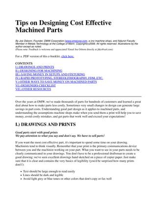
  • 21. and limitations in wall thickness (.020" or .5mm is common). In addition, although RP parts can be reasonably accurate, they still do not reach the level of precision of CNC machining. V.) OTHER WAYS TO SAVE MONEY ON MACHINED PARTS Small increased in part quantity can make a large difference in per-unit cost Per-unit part cost is very sensitive to the number of parts run. Sometimes a customer can't understand how a single part can cost $300 when 10 of the same part might cost $50. The reason is usually lies in setup and programming. CNC machines are very fast and efficient at producing parts when they are running. With small parts, the run time (the time the part is actually being cut by the machine tool) is usually short- often a very few minutes or less. However, it can take an hour or more of programming plus two hours of setup (getting vises placed, a fixture made, loading the machine with tools, offsetting tools and finding work coordinates, proving out the program, etc.) for even a relatively simple CNC part. In our example above, suppose the part takes an hour to program (@ $75/hr), two hours to setup, 10 minutes to run and a few minutes to deburr, clean up, etc. Let's call it 3.5 hours of labor, at $75/hr that equals $262.50, plus material cost (with shipping costs), and the total part cost nears $300. Now imagine there are 10 parts. In this case, there is a little more labor in deburring and clean up, let's call the total labor (less the run time) 4 hours vs. 3.5. That is $300 at $75/hr. Add in 100 minutes of run time (10 minutes each of 10 parts), and you have $425. Add material cost of a few dollars a part, shipping, etc. and you are at about $500. Hence the $300 vs. $50 part. Usually (and again there are always exceptions), the programming and setup costs are relatively fixed over a certain number of parts. These costs are a large proportion of the total part cost in small quantities. They get small amortized over large quantities. In the example above, the initial $300 programming and setup cost is less than $1 per part at quantities over 300. In this case, the run time becomes more critical, since the actual cost of the machine cutting now becomes the most expensive element and the limiting factor for cost. Since at some point the CNC machine cannot be optimized to cut any faster, the run time per part becomes a constant, and the part cost does not fall much more for higher quantity. To sum up, for the lowest per-unit cost, try to increase part quantity, even by a small number. Even a jump from one to two or three units can make a significant difference in per unit cost. The highest per-unit savings are usually found by increasing volume at low part quantities, at higher quantities, the per-unit cost doesn't drop as fast for an increase in volume.
  • 22. Illustration- As this graph illustrates, most of the decrease in per part cost occurs at the low end of the volume scale. Even an increase of one or two units ordered can significantly decrease per unit cost. Part families can also save money Often, at least part of the setup and programming time can be saved if several similar parts are ordered at the same time. The way many parts are programmed, it is relatively simple to leave out or add additional features to parts. Because similar parts are often fixtured the same way (e.g., using the same softjaws in a vise, or the same screw-down plate), the cost of setup is significantly reduced as well. Part families also often use similar tooling, so many tools can be re-used without having to reload and re-offset them in the CNC machine. If you are working on several different variations of similar parts, it is better to wait until you have finished several parts and ask for a quote on all of them at once. Note that in this case, the quote you receive will be for all the parts ordered at once- if you order just a single part from the group the part will need to be requoted. Go sparingly on high-tolerance features One of the best ways to save money on machined parts is to be careful to specify high tolerances only when you really need them. If the outside of a particular part is, for example, just a cosmetic visual surface, please let us know. Don't use the default CAD system dimensioning on everything. If some features only need a +-.020 accuracy instead of +-.002, take the time to put that in your print. It will definitely knock some cost off the part. Avoid specifying high flatness for thin materials. We often see things like a .0005" flatness
  • 23. specification for large, thin aluminum or stainless steel plates. It is very expensive to attempt to make parts to these types of tolerances, and large, thin sheets of materials like AL or stainless can not be trusted to hold their tolerances over time. There is a reason that surface plates are made of 4" thick granite. Also, avoid putting no tolerances or special notes on holes something is fitting into. If a particular pocket represents a cavity for a precision bearing press-fit, be sure to mention that on the print. That way the hole is sure to get the attention it needs from the machinist. Treat your machine shop professionally If you want the best out of your machine shop, it's important to treat them well. People like to do business with people they like, and it stands to reason that favorite customers get special attention. Here are a few do's and don'ts regarding machine shop proprieties: DO communicate regularly with your shop, call them if you perceive a problem. Don't let problems simmer. Do work with them to resolve issues fairly. Cutting metal to high tolerances is an extremely difficult art, and some mistakes are bound to happen. DO consult with your shop on design issues. Unless you've spent years of your life working as a machinist, don't assume you know more about manufacturing issues than they do. Virtually all professional machinists have many years of training. Many have advanced degrees. Treat them as peers, not as subordinates. DO pay your bills on time. Nearly all shops pay close attention to this. There is no question that fast paying customers get treated better. DON'T use your shop as a free quoting service to scope out the cost of proposed projects. Quotes are expensive for a shop. Only request quotes for jobs the shop has a fair chance to getting. Don't quote out jobs to more than 2 or 3 shops. Don't expect a shop to continue to quote multiple jobs without winning some work. DON'T try to beat a shop down on part costs. Do ask design advice on how part costs can be reduced. Treat your shop as part of your manufacturing team, and foster communication between design and manufacturing. VI.) DESIGNERS CHECKLIST Detailed Prints: Prints clearly legible Multiple views shown (3D if possible) Careful dimensioning and tolerancing provided Material specified Finish specified (if desired) Part numbers assigned to parts Revision history shown.
  • 24. Part function clearly described Has CAD format file been supplied? Does CAD file match dimensioned print? Design Issues: Inside corners rounded to take into account endmill diameters Depth of pockets not excessive for endmill length Deep pockets with small inside radii avoided Holes not tapped too deep Clearances provided for spindle and tools Parts are easy to fixture Setups minimized Other: Group parts in similar families Maximize volumes for per-unit cost reduction VII.) OTHER RESOURCES Jim Harvey's excellent book "Machine Shop Trade Secrets" has a section called "Help for Engineers" which covers many design issues from a machinist's perspective. The book is available from ProShop Publishing (www.proshoppublishing.com) Joe Martin, of Sherline Products, touches on a number of important issues in the manufacturing section of his on-line book, "Making Money the Old Fashioned Way" (www.sherline.com/business.htm). His paper book "Tabletop Machining" also contains some very useful information. Checkout his excellent website at www.sherline.com Newsgroups, such as alt.machines.cnc, can be wonderful sources for information. Anthony, a prolific and knowledgeable poster to this newsgroup created an excellent list of advice on reducing the cost of machining. With his permission, I've created a link to it here: Anthony's Advice on Cost-effective Part Design Click here to return to the OMW Corporation Website